

Online proceedings - EDA Publishing Association
Online proceedings - EDA Publishing Association
Online proceedings - EDA Publishing Association

Create successful ePaper yourself
Turn your PDF publications into a flip-book with our unique Google optimized e-Paper software.
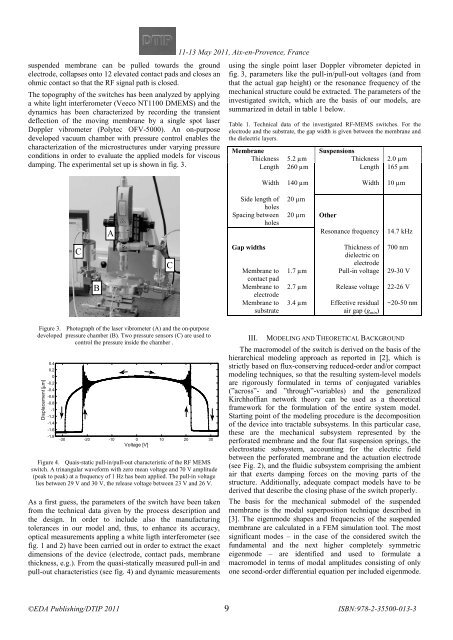
suspended membrane can be pulled towards the ground<br />
electrode, collapses onto 12 elevated contact pads and closes an<br />
ohmic contact so that the RF signal path is closed.<br />
The topography of the switches has been analyzed by applying<br />
a white light interferometer (Veeco NT1100 DMEMS) and the<br />
dynamics has been characterized by recording the transient<br />
deflection of the moving membrane by a single spot laser<br />
Doppler vibrometer (Polytec OFV-5000). An on-purpose<br />
developed vacuum chamber with pressure control enables the<br />
characterization of the microstructures under varying pressure<br />
conditions in order to evaluate the applied models for viscous<br />
damping. The experimental set up is shown in fig. 3.<br />
11-13 <br />
May 2011, Aix-en-Provence, France<br />
<br />
using the single point laser Doppler vibrometer depicted in<br />
fig. 3, parameters like the pull-in/pull-out voltages (and from<br />
that the actual gap height) or the resonance frequency of the<br />
mechanical structure could be extracted. The parameters of the<br />
investigated switch, which are the basis of our models, are<br />
summarized in detail in table 1 below.<br />
Table 1. Technical data of the investigated RF-MEMS switches. For the<br />
electrode and the substrate, the gap width is given between the membrane and<br />
the dielectric layers.<br />
Membrane<br />
Suspensions<br />
Thickness 5.2 µm Thickness 2.0 µm<br />
Length 260 µm Length 165 µm<br />
Width 140 µm Width 10 µm<br />
A<br />
Side length of<br />
holes<br />
Spacing between<br />
holes<br />
20 µm<br />
20 µm Other<br />
Resonance frequency<br />
14.7 kHz<br />
C<br />
B<br />
C<br />
Gap widths<br />
Membrane to<br />
contact pad<br />
Membrane to<br />
electrode<br />
Membrane to<br />
substrate<br />
Thickness of 700 nm<br />
dielectric on<br />
electrode<br />
1.7 µm Pull-in voltage 29-30 V<br />
2.7 µm Release voltage 22-26 V<br />
3.4 µm Effective residual<br />
air gap (g min )<br />
~20-50 nm<br />
Figure 3. Photograph of the laser vibrometer (A) and the on-purpose<br />
developed pressure chamber (B). Two pressure sensors (C) are used to<br />
control the pressure inside the chamber .<br />
Displacement [μm]<br />
0.4<br />
0.2<br />
0<br />
-0.2<br />
-0.4<br />
-0.6<br />
-0.8<br />
-1<br />
-1.2<br />
-1.4<br />
-1.6<br />
-1.8<br />
-30 -20 -10 0 10 20 30<br />
Voltage [V]<br />
Figure 4. Quais-static pull-in/pull-out characteristic of the RF MEMS<br />
switch. A trinangular waveform with zero mean voltage and 70 V amplitude<br />
(peak to peak) at a frequency of 1 Hz has been applied. The pull-in voltage<br />
lies between 29 V and 30 V, the release voltage between 23 V and 26 V.<br />
As a first guess, the parameters of the switch have been taken<br />
from the technical data given by the process description and<br />
the design. In order to include also the manufacturing<br />
tolerances in our model and, thus, to enhance its accuracy,<br />
optical measurements appling a white ligth interferometer (see<br />
fig. 1 and 2) have been carried out in order to extract the exact<br />
dimensions of the device (electrode, contact pads, membrane<br />
thickness, e.g.). From the quasi-statically measured pull-in and<br />
pull-out characteristics (see fig. 4) and dynamic measurements<br />
III. MODELING AND THEORETICAL BACKGROUND<br />
The macromodel of the switch is derived on the basis of the<br />
hierarchical modeling approach as reported in [2], which is<br />
strictly based on flux-conserving reduced-order and/or compact<br />
modeling techniques, so that the resulting system-level models<br />
are rigorously formulated in terms of conjugated variables<br />
(”across”- and ”through”-variables) and the generalized<br />
Kirchhoffian network theory can be used as a theoretical<br />
framework for the formulation of the entire system model.<br />
Starting point of the modeling procedure is the decomposition<br />
of the device into tractable subsystems. In this particular case,<br />
these are the mechanical subsystem represented by the<br />
perforated membrane and the four flat suspension springs, the<br />
electrostatic subsystem, accounting for the electric field<br />
between the perforated membrane and the actuation electrode<br />
(see Fig. 2), and the fluidic subsystem comprising the ambient<br />
air that exerts damping forces on the moving parts of the<br />
structure. Additionally, adequate compact models have to be<br />
derived that describe the closing phase of the switch properly.<br />
The basis for the mechanical submodel of the suspended<br />
membrane is the modal superposition technique described in<br />
[3]. The eigenmode shapes and frequencies of the suspended<br />
membrane are calculated in a FEM simulation tool. The most<br />
significant modes – in the case of the considered switch the<br />
fundamental and the next higher completely symmetric<br />
eigenmode – are identified and used to formulate a<br />
macromodel in terms of modal amplitudes consisting of only<br />
one second-order differential equation per included eigenmode.<br />
9


