

Online proceedings - EDA Publishing Association
Online proceedings - EDA Publishing Association
Online proceedings - EDA Publishing Association

You also want an ePaper? Increase the reach of your titles
YUMPU automatically turns print PDFs into web optimized ePapers that Google loves.
one of the bonding methods is best adequate for different<br />
ranges of channel dimensions.<br />
Laminating a DFR layer on top of the channel layer was<br />
the most comfortable way of closing since it is the simplest.<br />
As shown in Fig. 4 a), channels were tightly sealed by this<br />
method at an optimum lamination temperature of 75 °C [6].<br />
However, for channels exceeding widths of 250 µm, the lid<br />
DFR layer sagged into the broad chambers and stuck to the<br />
bottom (Fig. 4b)). Therefore, this bonding method is limited<br />
to smaller channel structures. Though, for channels smaller<br />
than 20 µm, unbonded spots occurred at the channel edges.<br />
With respect to biomedical applications, it is desirable for<br />
the biological fluid to be in contact with as few materials as<br />
possible in order to avoid interaction of biological<br />
substances with other materials. On this score, combination<br />
of DFR as the channel layer with lamination of DFR as a lid<br />
forms the simplest way of fabricating a complete<br />
microfluidic system in which the biological fluid is in<br />
contact only with DFR and no other material. Still, as<br />
described above, this proceeding is best applicable for<br />
moderate channel dimensions between 20 µm and 250 µm.<br />
Based on the second bonding approach, the application<br />
range was extended to smaller and larger channel<br />
dimensions. As DFR was laminated onto a PMMA lid plate<br />
at first, sagging of DFR into broad channels or chambers<br />
was obviated entirely. This bonding technique did not<br />
involve any constraints for dimensions of the channels to be<br />
covered. However, if the whole system is supposed to<br />
consist of DFR, channel widths are restrained to aspect<br />
ratios lower than 2:1. Alternatively, smaller channels<br />
fabricated from SU-8 can also be sealed by DFR resulting in<br />
an equally stable bond. Although two materials (SU-8 and<br />
DFR) will be in direct contact with the biological<br />
substances, these materials are chemically very similar.<br />
Yet, when SU-8 is chosen as the channel layer, SU-8 can<br />
also be employed as adhesive bonding layer using the third<br />
bonding approach. This method also revealed stable and<br />
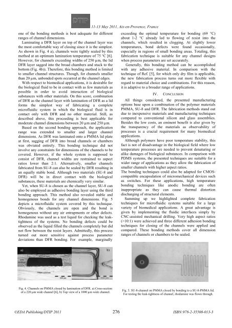
homogenous bonds for any channel dimensions. Fig. 5<br />
depicts a microfluidic system covered by this technique.<br />
Obviously, the channels are open and the bond is<br />
homogenous without any air entrapments or other defects.<br />
Rhodamine was used as a test liquid for checking the leaktightness<br />
of the systems. No bonding defects could be<br />
observed as the liquid filled the channels completely but did<br />
not flow between the resist layers. Admittedly, this process<br />
turned out more sensitive against process parameter<br />
deviations than DFR bonding. For example, marginally<br />
11-13 <br />
May 2011, Aix-en-Provence, France<br />
<br />
exceeding the optimal temperature for bonding (69 °C)<br />
about 1-2 °C already led to flowing of resist into the<br />
channels, which resulted in clogging. At slightly lower<br />
temperatures, bond defects were found occasionally,<br />
especially in regions of small bonding areas. Totaling, this<br />
fabrication technique is suitable for any channel designs<br />
when process parameters are set accurately.<br />
Generally, this bonding method can be accomplished<br />
with any adhesive material. In comparison with the<br />
technique of Ref. [5], for which only dry film is applicable,<br />
the new fabrication process turns out more flexible with<br />
regard to material choice and combinations. For this reason,<br />
it is adaptive to a broader range of applications.<br />
IV. CONCLUSION<br />
All things considered, the presented manufacturing<br />
options base upon a combination of the polymer materials<br />
PMMA, SU-8 and DFR. The fabrication methods stand out<br />
due to inexpensive materials and manufacturing techniques<br />
compared to conventional silicon and glass assemblies.<br />
Besides the low costs, an eminent benefit is also given by<br />
the transparency of the materials as observability of<br />
processes is a crucial requirement for many biomedical<br />
applications.<br />
Although polymers have poor temperature stability, this<br />
fact is not of disadvantage in the biological field where low<br />
temperature processes are needed to prevent denaturing or<br />
alike damages of biological substances. In comparison with<br />
PDMS systems, the presented techniques are suitable for a<br />
wider range of applications as they allow the fabrication of<br />
smaller channels with higher aspect ratios.<br />
The bonding techniques could also be adapted for CMOScompatible<br />
encapsulation of micromechanical devices such<br />
as switches. For these applications, high temperature<br />
bonding techniques like anodic bonding are often<br />
inappropriate as they can cause thermal distortion<br />
discharging of structural elements.<br />
Summing up we highlighted complete fabrication<br />
techniques for microfluidic systems suitable for a large<br />
variety of biomedical applications. A great advantage is<br />
given by implementing the fluidic interfaces simply by<br />
CNC-assisted mechanical drilling. Very high aspect ratios<br />
(>10:1) were achieved and three different adhesion bonding<br />
techniques for closing of the channels were applied and<br />
compared. These bonding methods cover all dimension<br />
ranges of channels or chambers to be sealed.<br />
a) b)<br />
Fig. 4. Channels on PMMA closed by lamination of DFR. a) Cross-section<br />
of a 220 µm wide channel [6], b) Top view of a 1000 µm wide channel.<br />
Fig. 5. SU-8-channel on PMMA closed by bonding to a SU-8-PMMA lid.<br />
For testing the leak-tightness of channel, rhodamine was flown through.<br />
276


