

Online proceedings - EDA Publishing Association
Online proceedings - EDA Publishing Association
Online proceedings - EDA Publishing Association

You also want an ePaper? Increase the reach of your titles
YUMPU automatically turns print PDFs into web optimized ePapers that Google loves.
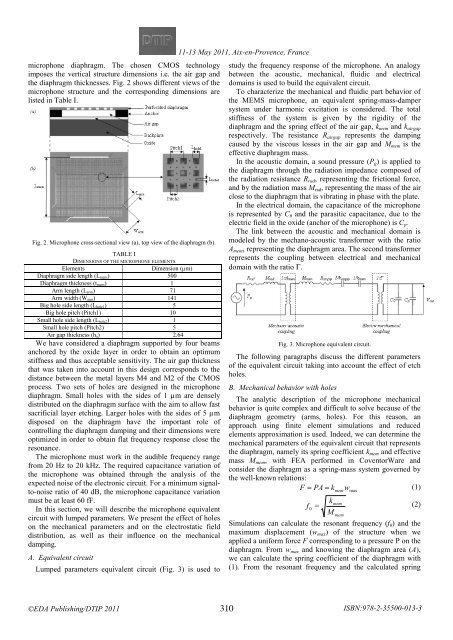
microphone diaphragm. The chosen CMOS technology<br />
imposes the vertical structure dimensions i.e. the air gap and<br />
the diaphragm thicknesses. Fig. 2 shows different views of the<br />
microphone structure and the corresponding dimensions are<br />
listed in Table I.<br />
Fig. 2. Microphone cross-sectional view (a), top view of the diaphragm (b).<br />
TABLE I<br />
DIMENSIONS OF THE MICROPHONE ELEMENTS<br />
Elements<br />
Dimension (µm)<br />
Diaphragm side length (L mem) 500<br />
Diaphragm thickness (t mem) 1<br />
Arm length (L arm) 71<br />
Arm width (W arm) 141<br />
Big hole side length (L hole1) 5<br />
Big hole pitch (Pitch1) 10<br />
Small hole side length (L hole2) 1<br />
Small hole pitch (Pitch2) 5<br />
Air gap thickness (h a) 2.64<br />
We have considered a diaphragm supported by four beams<br />
anchored by the oxide layer in order to obtain an optimum<br />
stiffness and thus acceptable sensitivity. The air gap thickness<br />
that was taken into account in this design corresponds to the<br />
distance between the metal layers M4 and M2 of the CMOS<br />
process. Two sets of holes are designed in the microphone<br />
diaphragm. Small holes with the sides of 1 µm are densely<br />
distributed on the diaphragm surface with the aim to allow fast<br />
sacrificial layer etching. Larger holes with the sides of 5 µm<br />
disposed on the diaphragm have the important role of<br />
controlling the diaphragm damping and their dimensions were<br />
optimized in order to obtain flat frequency response close the<br />
resonance.<br />
The microphone must work in the audible frequency range<br />
from 20 Hz to 20 kHz. The required capacitance variation of<br />
the microphone was obtained through the analysis of the<br />
expected noise of the electronic circuit. For a minimum signalto-noise<br />
ratio of 40 dB, the microphone capacitance variation<br />
must be at least 60 fF.<br />
In this section, we will describe the microphone equivalent<br />
circuit with lumped parameters. We present the effect of holes<br />
on the mechanical parameters and on the electrostatic field<br />
distribution, as well as their influence on the mechanical<br />
damping.<br />
A. Equivalent circuit<br />
Lumped parameters equivalent circuit (Fig. 3) is used to<br />
11-13 <br />
May 2011, Aix-en-Provence, France<br />
<br />
study the frequency response of the microphone. An analogy<br />
between the acoustic, mechanical, fluidic and electrical<br />
domains is used to build the equivalent circuit.<br />
To characterize the mechanical and fluidic part behavior of<br />
the MEMS microphone, an equivalent spring-mass-damper<br />
system under harmonic excitation is considered. The total<br />
stiffness of the system is given by the rigidity of the<br />
diaphragm and the spring effect of the air gap, k mem and k airgap<br />
respectively. The resistance R airgap represents the damping<br />
caused by the viscous losses in the air gap and M mem is the<br />
effective diaphragm mass.<br />
In the acoustic domain, a sound pressure (P g ) is applied to<br />
the diaphragm through the radiation impedance composed of<br />
the radiation resistance R rad , representing the frictional force,<br />
and by the radiation mass M rad , representing the mass of the air<br />
close to the diaphragm that is vibrating in phase with the plate.<br />
In the electrical domain, the capacitance of the microphone<br />
is represented by C 0 and the parasitic capacitance, due to the<br />
electric field in the oxide (anchor of the microphone) is C p .<br />
The link between the acoustic and mechanical domain is<br />
modeled by the mechano-acoustic transformer with the ratio<br />
A mem , representing the diaphragm area. The second transformer<br />
represents the coupling between electrical and mechanical<br />
domain with the ratio Γ.<br />
Fig. 3. Microphone equivalent circuit.<br />
The following paragraphs discuss the different parameters<br />
of the equivalent circuit taking into account the effect of etch<br />
holes.<br />
B. Mechanical behavior with holes<br />
The analytic description of the microphone mechanical<br />
behavior is quite complex and difficult to solve because of the<br />
diaphragm geometry (arms, holes). For this reason, an<br />
approach using finite element simulations and reduced<br />
elements approximation is used. Indeed, we can determine the<br />
mechanical parameters of the equivalent circuit that represents<br />
the diaphragm, namely its spring coefficient k mem and effective<br />
mass M mem , with FEA performed in CoventorWare and<br />
consider the diaphragm as a spring-mass system governed by<br />
the well-known relations:<br />
mem==<br />
maxwkP (1) AF<br />
kmem<br />
=f<br />
(2)<br />
0<br />
M<br />
mem<br />
Simulations can calculate the resonant frequency (f 0 ) and the<br />
maximum displacement (w max ) of the structure when we<br />
applied a uniform force F corresponding to a pressure P on the<br />
diaphragm. From w max and knowing the diaphragm area (A),<br />
we can calculate the spring coefficient of the diaphragm with<br />
(1). From the resonant frequency and the calculated spring<br />
310<br />
ISBN:978-2-35500-013-3


