

Online proceedings - EDA Publishing Association
Online proceedings - EDA Publishing Association
Online proceedings - EDA Publishing Association

You also want an ePaper? Increase the reach of your titles
YUMPU automatically turns print PDFs into web optimized ePapers that Google loves.
11-13 <br />
May 2011, Aix-en-Provence, France<br />
PET layer which is solid relative to a single PDMS<br />
<br />
PDMS<br />
membrane of the same thickness. Therefore the lens<br />
membrane exhibits good uniformity despite its large area.<br />
spacer wall<br />
II. DEVICE FABRICATION<br />
Across section of the produced adaptive lens is shown in<br />
Fig.1. Firstly a 2mm thick PDMS layer is fabricated using a<br />
mixture of PDMS base 184 from Dow Corning and crosslinking<br />
agent at a mass ratio of 10 to 1. The largest part of<br />
the mixture is degassed within a cylindrical tank and leave<br />
more than one hour to allow a natural spread by gravity of<br />
the material into the tank. Thus we can get a very flat<br />
surface. Then the material is cured for an hour at 70°C<br />
within the cylindrical container for reticulation. The<br />
thickness is calculated by knowing the diameter of the<br />
cylindrical tank and the weight difference before and after<br />
filling. After reticulation the PDMS is removed from the<br />
container. A circular hole of 30mm is then opened through<br />
the spacer to form the reservoir side-walls. A 6mm channel<br />
long is also formed from the inner to the outer wall of the<br />
spacer in order to accommodate two tubes as shown in<br />
Fig.1(a). The tubes have inner diameter of 0.3mm and outer<br />
diameter of 1.5mm. These manufacturing steps can be<br />
easily enhanced by the completion of a resin mold (in SU-8<br />
for example) on a silicon or glass wafer. The remaining<br />
non-cured PDMS mixture is also degassed and then spin<br />
coated on to a 75µm thick PET layer at a speed of 1200 rpm<br />
for 20 seconds. (PDMS thickness on PET 50 µm) The<br />
PDMS-coated PET is also placed at 70°C for an hour in<br />
order to cure the PDMS coating. The reason for using the<br />
PET layer is for increasing the rigidity of the flexible<br />
membrane of the lens. This eliminates any non-uniformity<br />
on the membrane surface due to the fabrication and due to<br />
the weight of the liquid as the lens is placed vertically. The<br />
PDMS coating of the PET is used for adhesion purposes. To<br />
elaborate further, the PDMS spacer and the PDMS-coated<br />
PET are etched using oxygen plasma. The oxygen plasma of<br />
PDMS results in the creation of free radicals on the PDMS<br />
surface. After the plasma etching, the PDMS spacer is<br />
placed on top of the PDMS-coated PET so as to be in<br />
contact with the spin-coated PDMS layer. The present of the<br />
free radicals ensures a strong adhesion between the two<br />
PDMS surfaces.<br />
The Young’s modulus of PDMS is in the range of MPa<br />
(0,2 Mpa more precisely) while that of PET is about 3000<br />
Mpa, ie three decade above. As the thicknesses have the<br />
same order of magnitude (50 µm for PDMS and 75 µm for<br />
PET), the deformation is overwhelmingly governed by the<br />
properties of PET.<br />
The sealed reservoir is then filled with de-ionized water<br />
using a commercially available micro-pump, produced by<br />
Bartels Mikrotechnik GmbH. The micro-pump is connected<br />
to one of the two tubes and the second tube is used for<br />
allowing the air to exit from the sealed reservoir. The<br />
introduction of the liquid in the reservoir is shown in Fig.2.<br />
Fig.2 (d) shows that no air remains within the reservoir at<br />
the end of the process. The internal dimensions of the<br />
system are large enough not to ask problems due to<br />
capillary forces.<br />
Glass<br />
Substrate<br />
PDMS<br />
coating<br />
PDMS<br />
spacer wall<br />
Glass Substrate<br />
Tubes<br />
(a)<br />
Liquid<br />
reservoir<br />
PET<br />
(b)<br />
Liquid reservoir<br />
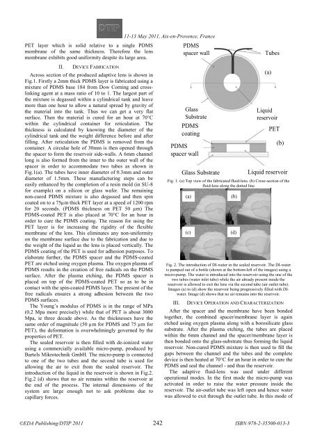
Fig. 1. (a) Top view of the fabricated fluid-lens. (b) Cross-section of the<br />
fluid-lens along the dotted line<br />
(a)<br />
(c)<br />
(b)<br />
(d)<br />
Fig. 2. The introduction of DI-water in the sealed reservoir. The DI-water<br />
is pumped out of a bottle (shown at the bottom-left of the images) using a<br />
micro-pump. The water is introduced into the reservoir using the one of the<br />
two tubes (water inlet tube) while the air already present inside the<br />
reservoir is allowed to exit the lens via the second tube (air outlet tube).<br />
Images (a) to (d) show the reservoir being progressively filled with DIwater.<br />
Image (d) shows that no air remains into the reservoir.<br />
III. DEVICE OPERATION AND CHARACTERIZATION<br />
After the spacer and the membrane have been bonded<br />
together, the combined spacer/membrane layer is again<br />
etched using oxygen plasma along with a borosilicate glass<br />
substrate. After the plasma etching, the tubes are placed<br />
within the 6mm channel and the spacer/membrane layer is<br />
then bonded onto the glass-substrate thus forming the liquid<br />
reservoir. Non-cured PDMS mixture is then used to fill the<br />
gaps between the channel and the tubes and the complete<br />
device is then heated at 70°C for an hour in order to cure the<br />
PDMS and seal the channel - and thus the reservoir.<br />
The adaptive fluid-lens was used under different<br />
operational modes. In the first mode the micro-pump was<br />
activated in order to raise the water pressure inside the<br />
reservoir. The air-outlet tube was left open and hence water<br />
was allowed to exit through the outlet tube. In this mode of<br />
242


