You also want an ePaper? Increase the reach of your titles
YUMPU automatically turns print PDFs into web optimized ePapers that Google loves.
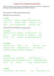
Typical cabling connections on a 64 fader console<br />
In both of the CAT5 cabling examples outlined below, the USB to CAT5<br />
(USB-Serial) converter cable (supplied) should be connected from the<br />
<strong>Genesys</strong> computer and then into the first AD/DA (or Monitor) card.<br />
This cable must only be connected once the <strong>Genesys</strong> system is fully<br />
booted and the <strong>Genesys</strong> software is running.<br />
CAT5 connections on systems with AD/DA Monitor card<br />
Channel Slave Audio Link Channel Slave Audio Link Channel Slave Audio Link Channel Slave Audio Link<br />
1 2 3 1 2 3 1 2 3 1 2 3 1 2 3 1 2 3 1 2 3 1 2 3<br />
1 - 8 9 – 16 17 – 24 25 – 32 Monitoring 33 – 40 41 – 48 49 – 56 57 - 64<br />
Master Slave Master Slave Master Slave Master Slave<br />
In Out In Out In Out In Out In<br />
USB to CAT5 converter cable - into Serial In on the Monitor<br />
card, then out of both Serial Outs, one to feed<br />
<strong>Genesys</strong> each side of the console.<br />
computer<br />
The cards in positions 1-8, 17-24, 33-40 and 49-56 are AD/DA Master<br />
cards, each of them connected to their Slave cards by 3 x CAT5<br />
connectors: Serial 1 on the Master connects to Serial 1 on the Slave and<br />
so on.<br />
There are two chains of CAT5 connectors (for comms purposes) shown at<br />
the bottom of the above diagram that start from the central Monitoring<br />
AD/DA card, one for the Left side and one for the Right side of the<br />
console.<br />
From the central Monitoring AD/DA, connect Out to In, Out to In etc<br />
spreading out from the centre of the console.<br />
All of these connections are made on the rear of the AD/DA cards<br />
themselves.<br />
- 140 -