- Page 1 and 2:
LTV ® 1100 Ventilator Operator’s
- Page 3 and 4:
Warranty CareFusion warrants that t
- Page 5 and 6:
Notice To Operators Unsafe Operatio
- Page 7 and 8:
Breath Rate .......................
- Page 9 and 10:
High Pressure Alarm Delay .........
- Page 11 and 12:
Installation and Setup ............
- Page 13 and 14:
Operator’s Safety Information All
- Page 15 and 16:
WARNING Battery run time - When the
- Page 17 and 18:
AVERTISSEMENT Personnel non qualifi
- Page 19 and 20:
AVERTISSEMENT Modes Vérification e
- Page 21 and 22:
Cautions CAUTION Ventilator Sterili
- Page 23 and 24:
CAUTION External Battery Pack - The
- Page 25 and 26:
ATTENTION Nettoyage du panneau fron
- Page 27 and 28:
Symbols Symbol Compliance 1 Title A
- Page 29 and 30:
Indications for Use The LTV ® 1100
- Page 31 and 32:
Information/Assistance For addition
- Page 33 and 34:
Volume Control Breaths For Volume C
- Page 35 and 36:
Spontaneous Breaths For Spontaneous
- Page 37 and 38:
SIMV Mode SIMV mode is selected whe
- Page 39 and 40:
NPPV Mode The ventilator provides N
- Page 41 and 42:
Volume Ventilation The LTV ® 1100
- Page 43 and 44:
Setting a Control There are 5 kinds
- Page 45 and 46:
Bright, Dim and Blank Control Displ
- Page 47 and 48:
Control Locking The front panel con
- Page 49 and 50:
Breath Rate Use the Breath Rate con
- Page 51 and 52:
High Pressure Limit Use the High Pr
- Page 53 and 54:
Low Pressure The Low Pressure alarm
- Page 55 and 56:
On/Standby This button switches the
- Page 57 and 58:
PEEP Control The PEEP control estab
- Page 59 and 60:
Select Use this button to change th
- Page 61 and 62:
Set Value Knob Use the Set Value kn
- Page 63 and 64:
Tidal Volume Use the Tidal Volume c
- Page 65 and 66:
6-18 Operator’s Manual - LTV ® 1
- Page 67 and 68:
Battery Level The Battery Level ind
- Page 69 and 70: Charge Status The Charge Status ind
- Page 71 and 72: NPPV The NPPV 20 indicator LED is l
- Page 73 and 74: Automatic or Manual Data Display Sc
- Page 75 and 76: I:Ecalc xx:xx The Calculated I:E ra
- Page 77 and 78: Alarms APNEA, APNEA xx bpm When the
- Page 79 and 80: BAT EMPTY (cont.) NOTE When the bat
- Page 81 and 82: BAT LOW (cont) NOTE Internal Batter
- Page 83 and 84: DEFAULTS (cont.) The factory-set de
- Page 85 and 86: DISC/SENSE When the ventilator dete
- Page 87 and 88: HIGH PEEP When the patient circuit
- Page 89 and 90: High PRES (cont.) The HIGH PRES ala
- Page 91 and 92: INOP An INOP alarm is generated whe
- Page 93 and 94: LOW PEEP When the patient circuit p
- Page 95 and 96: NO CAL DATA, NO CAL Monitor Display
- Page 97 and 98: POWER LOW When the ventilator is op
- Page 99 and 100: RESET / RESET 1 A RESET or a RESET
- Page 101 and 102: SBT > f When the Spontaneous Breath
- Page 103 and 104: SBT > f/Vt When the Spontaneous Bre
- Page 105 and 106: XDCR FAULT When a transducer autoze
- Page 107 and 108: H&L PEEP OFF The H&L PEEP OFF messa
- Page 109 and 110: LO f/Vt OFF The LO f/Vt OFF message
- Page 111 and 112: SBT TIME The SBT TIME message is di
- Page 113 and 114: Navigating the Extended Features Me
- Page 115 and 116: Apnea Interval Use this menu item t
- Page 117 and 118: Patient Assist Use the PNT ASSIST m
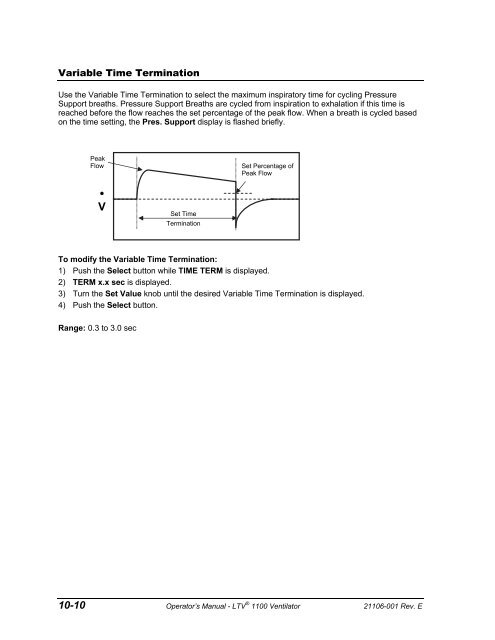
- Page 119: Variable Rise Time Use the Variable
- Page 123 and 124: Leak Compensation Use the Leak Comp
- Page 125 and 126: Control Unlock Use the Control Unlo
- Page 127 and 128: Set Date Use the Set Date option to
- Page 129 and 130: PIP LED Use the PIP LED option to t
- Page 131 and 132: Sigh Breath Use the Sigh Breath fea
- Page 133 and 134: Turning Leak Test Query on or off 1
- Page 135 and 136: SBT Operations (cont.) When the Spo
- Page 137 and 138: SBT Quick Start Feature In addition
- Page 139 and 140: Bi-directional Flow Transducer Diff
- Page 141 and 142: Real Time Transducers Use the Real
- Page 143 and 144: 10-32 Operator’s Manual - LTV ®
- Page 145 and 146: To enable the Ventilator Checkout m
- Page 147 and 148: Display Test Use the Display Test t
- Page 149 and 150: Control Test Use the Control Test t
- Page 151 and 152: Leak Test Use the Leak Test to test
- Page 153 and 154: Vent Inop Alarm Test Use the Vent I
- Page 155 and 156: Exit To exit the vent check mode an
- Page 157 and 158: AVERTISSEMENT Mode de circuit du pa
- Page 159 and 160: The Power On Self Tests 43 (POST) a
- Page 161 and 162: Procedure for Control Mode Set Up S
- Page 163 and 164: Procedure for SIMV Mode Set Up Set
- Page 165 and 166: Procedure for NPPV Mode Set Up Set
- Page 167 and 168: LTV ® Ventilator Settings Checklis
- Page 169 and 170: Cleaning or replacing the Fan Filte
- Page 171 and 172:
Cleaning the Exhalation Valve and R
- Page 173 and 174:
ATTENTION Nettoyage du piège à ea
- Page 175 and 176:
To clean the exhalation valve, sens
- Page 177 and 178:
13-10 Operator’s Manual - LTV ®
- Page 179 and 180:
Using the AC Adapter To run the ven
- Page 181 and 182:
2) Connect the power connector on t
- Page 183 and 184:
Using the Automobile Cigarette Ligh
- Page 185 and 186:
CAUTION Release Button - To avoid d
- Page 187 and 188:
Replacing the Automobile Adapter Fu
- Page 189 and 190:
14-12 Operator’s Manual - LTV ®
- Page 191 and 192:
Displays and Buttons Some of the sy
- Page 193 and 194:
Symptoms Possible Causes What to Do
- Page 195 and 196:
Ventilator Performance Symptoms Pos
- Page 197 and 198:
Symptoms Possible Causes What to Do
- Page 199 and 200:
Symptoms Possible Causes What to Do
- Page 201 and 202:
Symptoms Possible Causes What to Do
- Page 203 and 204:
Power and Battery Operation Problem
- Page 205 and 206:
Alarms Many alarms such as HIGH PRE
- Page 207 and 208:
Symptoms Possible Causes What to Do
- Page 209 and 210:
Symptoms Possible Causes What to Do
- Page 211 and 212:
Symptoms Possible Causes What to Do
- Page 213 and 214:
Symptoms Possible Causes What to Do
- Page 215 and 216:
15-26 Operator’s Manual - LTV ®
- Page 217 and 218:
Control Range Tolerance Tidal Volum
- Page 219 and 220:
Fixed Alarms Control Range Toleranc
- Page 221 and 222:
Displays Display Range Tolerance Ai
- Page 223 and 224:
Power Feature Range Tolerance / Ind
- Page 225 and 226:
EMC and RF Environments The followi
- Page 227 and 228:
Table 203 - 60601-1-2 © IEC:2001(E
- Page 229 and 230:
A-14 Operator’s Manual - LTV ® 1
- Page 231 and 232:
Service Assistance For assistance i
- Page 233 and 234:
Protective Boots Rubberized protect
- Page 235 and 236:
Item (1), Protective Boot, Upper (1
- Page 237 and 238:
Protective Boot Installation Suppli
- Page 239 and 240:
To Install the Lower Protective Boo
- Page 241 and 242:
Patient Breathing Circuit - Connect
- Page 243 and 244:
Low Pressure O 2 Source This option
- Page 245 and 246:
Low Pressure O 2 Source (cont.) To
- Page 247 and 248:
Communications Port The Communicati
- Page 249 and 250:
3) If the remote alarm has a male B
- Page 251 and 252:
Ventilator Settings and Procedure P
- Page 253 and 254:
Procedure: Set the Low Min. Vol. al
- Page 255 and 256:
Ventilation flow enters the Flow Va
- Page 257 and 258:
5) Push the Select button. xx:even
- Page 259 and 260:
Code Event Name Event Associated Al
- Page 261 and 262:
Event Codes by Event Name Event Nam
- Page 263 and 264:
Event Name Code Event Associated Al
- Page 265 and 266:
TERM Control mode CPAP CPAP mode Di
- Page 267 and 268:
TERM Pressure support breath Pressu
- Page 269 and 270:
C Calculated Peak Flow · 6-16, 8-2
- Page 271 and 272:
NPPV Mode · 4-4, 10-11 Indicator