- Page 1 and 2:
DRIVE DDS Hardware manual Ref.1307
- Page 3 and 4:
GENERAL INDEX 1 DESCRIPTION .......
- Page 5 and 6:
Order example .....................
- Page 7 and 8:
DECLARATION OF CONFORMITY Manufactu
- Page 13 and 14:
Title DRIVE DDS. Hardware manual. T
- Page 15 and 16:
- SHIPPING CONDITIONS, STORAGE AND
- Page 17 and 18:
- VERSION HISTORY - The history of
- Page 19 and 20:
- SAFETY CONDITIONS - Read the foll
- Page 21 and 22:
Precautions during repairs Do not
- Page 23 and 24:
- ADDITIONAL NOTES - Install the DD
- Page 25 and 26:
DESCRIPTION 1 The DDS servo drive s
- Page 27 and 28:
1.2 General diagram See the schemat
- Page 29 and 30:
1.4 Environmental and operating con
- Page 31 and 32:
POWER SUPPLIES 2 The FAGOR power su
- Page 33 and 34:
PS-65A module Technical data T. H2/
- Page 35 and 36:
PS-65A. Connector description The n
- Page 37 and 38:
PS-25B4 module Technical data T. H2
- Page 39 and 40:
PS-25B4. Connector description The
- Page 41 and 42:
PS-25B4 Model currently in the cata
- Page 43 and 44:
Terminal strip to connect the Balla
- Page 45 and 46:
i WARNING. Before handling these le
- Page 47 and 48:
The internal circuits of the non-re
- Page 49 and 50:
Module power-up 1. For PS-65A power
- Page 51 and 52:
XPS modules Technical data T. H2/14
- Page 53 and 54:
Block diagram X1 ( RIBON CABLE ) X2
- Page 55 and 56:
i Lights indicating the status of t
- Page 57 and 58:
i Lights indicating the status of t
- Page 59 and 60:
Terminal strip to connect the Balla
- Page 61 and 62:
i F. H2/22 Version label of the APS
- Page 63 and 64:
The next table shows the signals an
- Page 65 and 66:
Module power-up 1. For the XPS-25 a
- Page 67 and 68:
i However: The RPS-80 supplies 80 k
- Page 69 and 70:
Power diagram Mains Mains Mains Mai
- Page 71 and 72:
Power derating graph / RPS-45 T. H2
- Page 73 and 74:
Block diagram LINE FEEDBACK L1' L2'
- Page 75 and 76:
RPS-75. Connector description The f
- Page 77 and 78:
RPS-20. Connector description The f
- Page 79 and 80:
ON STATUS DISPLAY Other elements B
- Page 81 and 82:
1x Terminal strip for connecting th
- Page 83 and 84:
i i WARNING. Never install an APS-2
- Page 85 and 86:
i 1x Other connectors X1 and X2 con
- Page 87 and 88:
1x NOTE. It is important to know th
- Page 89 and 90:
The next table shows the signals an
- Page 91 and 92:
2. The power supply checks the syst
- Page 93 and 94:
NOTE. When detecting an error, it w
- Page 95 and 96:
DRIVE MODULES 3 The drives that mak
- Page 97 and 98:
X3 X4 X5 X6 SL2 SL1 X3 X4 X5 X6 SL2
- Page 99 and 100:
T. H3/5 Technical characteristics o
- Page 101 and 102:
Current derating Drives for an sync
- Page 103 and 104:
I (Arms) Imax 70 60 50 40 In 30 20
- Page 105 and 106:
I (Arms) 80 70 60 50 40 30 Imax In
- Page 107 and 108:
For a switching frequency fc = 4 kH
- Page 109 and 110:
For a switching frequency fc = 8 kH
- Page 111 and 112:
Power derating The following graph
- Page 113 and 114:
Connector layout AXD/SPD 1.08/1.15
- Page 115 and 116:
AXD/SPD 1.35 These drive modules ha
- Page 117 and 118: AXD/SPD 3.100/3.150 These drive mod
- Page 119 and 120: MMC 1.08/1.15 These drive modules h
- Page 121 and 122: MMC 1.35 These drive modules have t
- Page 123 and 124: MMC 3.100/3.150 These drive modules
- Page 125 and 126: FUSE (250V) 2,5A(F) STATUS DISPLAY
- Page 127 and 128: X1 connector This connector may be
- Page 129 and 130: Deactivation of the Speed Enable in
- Page 131 and 132: X3. Direct feedback Having installe
- Page 133 and 134: V A V B F. H3/68 Characteristics of
- Page 135 and 136: X5 connector X5. RS-232 serial line
- Page 137 and 138: i i The description of the pinout o
- Page 139 and 140: Digital inputs characteristics Digi
- Page 141 and 142: Dip-Switches (DS1, DS2) DS1 DS2 F.
- Page 143 and 144: Characteristics of the digital inpu
- Page 145 and 146: 3.2 Compact drives When referring t
- Page 147 and 148: The following table shows other ele
- Page 149 and 150: Current derating Drives for an sync
- Page 151 and 152: For a switching frequency fc = 8 kH
- Page 153 and 154: 40 30 20 10 I (Arms) F. H3/102 Curr
- Page 155 and 156: Connector layout The connectors of
- Page 157 and 158: ACD/SCD 1.25 These drive modules ha
- Page 159 and 160: SCD 2.75 These drive modules have t
- Page 161 and 162: CMC 1.25 These drive modules have t
- Page 163 and 164: 24V ON STATUS DISPLAY BALLAST DC BU
- Page 165 and 166: x1 x1 The following table shows the
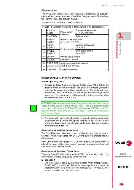
- Page 167: x1 X1 connector Compact drives inte
- Page 171 and 172: X3 connector This connector of the
- Page 173 and 174: With external incremental feedback
- Page 175 and 176: X4 connector X4. Motor feedback Con
- Page 177 and 178: i X6 connector This connector of th
- Page 179 and 180: x1 X7 connector X7. Status of the s
- Page 181 and 182: Pinout X7-ANALOG I/O, digital input
- Page 183 and 184: Analog outputs Associated with pins
- Page 185 and 186: Digital outputs characteristics Nam
- Page 187 and 188: i 3. Final stages: They display err
- Page 189 and 190: AUXILIARY MODULES 4 Besides the pow
- Page 191 and 192: 4.2 Chokes The chokes (inductances
- Page 193 and 194: 4.3 External Ballast resistors NOTE
- Page 195 and 196: ER+TH-18/x+FAN resistors with inter
- Page 197 and 198: Ohm value WARNING. When connecting
- Page 199 and 200: 4.4 Capacitor module This module st
- Page 201 and 202: i INFORMATION. In case of micro-sur
- Page 203 and 204: RESET OVER VOLTAGE OVER CURRENT ON
- Page 205 and 206: SELECTING CRITERIA 5 5.1 Selection
- Page 207 and 208: Motor speed calculation (rev/min) T
- Page 209 and 210: Third motor pre-selection Calculati
- Page 211 and 212: 5.2 Asynchronous spindle motor and
- Page 213 and 214: In the case of a drill, the bit is
- Page 215 and 216: T. H5/3 Different accelerations dep
- Page 217 and 218: 5.3 Drive selection When selecting
- Page 219 and 220:
Then, depending on the power for S3
- Page 221 and 222:
T. H5/8 Power supply selection when
- Page 223 and 224:
Non-FAGOR asynchronous spindle moto
- Page 225 and 226:
2. The power supply module must be
- Page 227 and 228:
T. H5/14 Selection of the mains con
- Page 229 and 230:
5.6 Ballast resistor selection guid
- Page 231 and 232:
When using compact drive modules th
- Page 233 and 234:
POWER LINE CONNECTION 6.1 Mains con
- Page 235 and 236:
6.2 Protection fuses i i To protect
- Page 237 and 238:
6.3 Differential breaker i On a DDS
- Page 239 and 240:
i MANDATORY. For machines whose ser
- Page 241 and 242:
6.6 Line inductance Line inductance
- Page 243 and 244:
i TN type mains Distribution diagra
- Page 245 and 246:
i IT type mains Distribution diagra
- Page 247 and 248:
CABLES 7 This chapter describes the
- Page 249 and 250:
7.2 Power cable. Motor-drive connec
- Page 251 and 252:
7.3 Motor feedback cables i i The a
- Page 253 and 254:
7.4 Direct feedback cable The direc
- Page 255 and 256:
7.5 Signal cables for control and c
- Page 257 and 258:
Their sales reference is: SFO-V-FLE
- Page 259 and 260:
7.6 RS232/RS422 BE adapter Before s
- Page 261 and 262:
PC-VT connection using an RS-232 ca
- Page 263 and 264:
RS-232 serial line cable between a
- Page 265 and 266:
RS-422 serial line cable between a
- Page 267 and 268:
INSTALLATION 8.1 Location 8 This ch
- Page 269 and 270:
Auxiliary modules Dissipated power
- Page 271 and 272:
EMC instructions for equipment inst
- Page 273 and 274:
See example of electrical installat
- Page 275 and 276:
A. Fan. Air output. It is recommend
- Page 277 and 278:
8.3 System installation Preparation
- Page 279 and 280:
8.4 Connection between modules Powe
- Page 281 and 282:
Ground connection MANDATORY. It is
- Page 283 and 284:
Connection to the external Ballast
- Page 285 and 286:
How to install an external Ballast
- Page 287 and 288:
How to install an external Ballast
- Page 289 and 290:
Ohm values WARNING. The Ohm value o
- Page 291 and 292:
8.5 Power supply connections i See
- Page 293 and 294:
8.6 Connection of the control and c
- Page 295 and 296:
i SERCOS ring connection The SERCOS
- Page 297 and 298:
Handling fiber optic cables FAGOR s
- Page 299 and 300:
Values that may be assigned to the
- Page 301 and 302:
SERCOS connection with a FAGOR 8055
- Page 303 and 304:
ISO GND CAN L SHIELD CAN H SHIELD P
- Page 305 and 306:
Once the display shows the desired
- Page 307 and 308:
CAN connection with a FAGOR 8055i C
- Page 309 and 310:
RS-232/422 serial line connection w
- Page 311 and 312:
8.7 Check the installation Check th
- Page 313 and 314:
FUNCTIONAL SAFETY 9 See section on
- Page 315 and 316:
9.2 Interface X3 X4 X5 X6 NODE OUT
- Page 317 and 318:
Considerations to bear in mind in t
- Page 319 and 320:
9.5 Risk analysis The machine manuf
- Page 321 and 322:
9.7 Response time FAGOR recommends
- Page 323 and 324:
9.9 Commissioning Check that each o
- Page 325 and 326:
9.11 Decommission and disposal The
- Page 327 and 328:
CONNECTION DIAGRAMS 10 10.1 SPD mod
- Page 329 and 330:
10.4 SCD compact drive with FM7 asy
- Page 331 and 332:
10.6 ACD compact drive with FXM syn
- Page 333 and 334:
i NOTE. Observe that a push-button
- Page 335 and 336:
i Brake control In some application
- Page 337 and 338:
BLOCK DIAGRAM OF THE DDS SYSTEM STA
- Page 339 and 340:
OPERATION DIAGRAM. PS-65A EMERG. ST
- Page 341 and 342:
OPERATION DIAGRAM. PS-25B4 EMERG. S
- Page 343 and 344:
OPERATION DIAGRAM. XPS-XX EMERG. ST
- Page 345 and 346:
OPERATION DIAGRAM. RPS-XX EMERG. ST
- Page 347 and 348:
10.13 Compact system diagrams with
- Page 349 and 350:
10.14 Diagrams of a mixed (combined
- Page 351 and 352:
OPERATION DIAGRAM Note 1. - KA3 is
- Page 353 and 354:
10.17 On-the-fly start/delta connec
- Page 355 and 356:
DIMENSIONS 11 When designing and bu
- Page 357 and 358:
11.3 Modular drive modules 255 (10.
- Page 359 and 360:
11.5 Mains filter 50 mm C L-1 C 50
- Page 361 and 362:
11.7 RPS chokes F. H11/7 Chokes RPS
- Page 363 and 364:
11.9 External Ballast resistors wit
- Page 365 and 366:
SALES REFERENCES 12 This chapter in
- Page 367 and 368:
Sales reference of the synchronous
- Page 369 and 370:
12.3 References of modular drives S
- Page 371 and 372:
12.5 References of positioning driv
- Page 373 and 374:
12.7 References of other elements S
- Page 375 and 376:
Sales reference of the SERCOS inter
- Page 377 and 378:
12.10 Module identification Each el
- Page 379 and 380:
COMPATIBILITY 13.1 Mains voltage 13
- Page 381 and 382:
13.6 VECON-3 board 13.7 VECON-4 boa
- Page 383 and 384:
13.15 CAPMOTOR-2 board and type of
- Page 386:
FAGOR AUTOMATION Fagor Automation S