Biomechanics and Medicine in Swimming XI
Biomechanics and Medicine in Swimming XI
Biomechanics and Medicine in Swimming XI

Create successful ePaper yourself
Turn your PDF publications into a flip-book with our unique Google optimized e-Paper software.
<strong>Biomechanics</strong><strong>and</strong>medic<strong>in</strong>e<strong>in</strong>swimm<strong>in</strong>gXi<br />
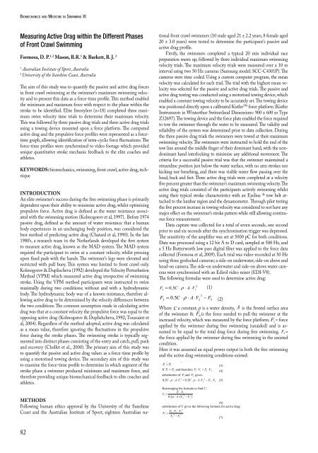
Measur<strong>in</strong>g Active Drag with<strong>in</strong> the Different Phases<br />
of Front Crawl Swimm<strong>in</strong>g<br />
Formosa, d. P. 1, 2 Mason, B.r. 1 & Burkett, B. J. 2<br />
1 Australian Institute of Sport, Australia<br />
2 University of the Sunsh<strong>in</strong>e Coast, Australia<br />
The aim of this study was to quantify the passive <strong>and</strong> active drag forces<br />
<strong>in</strong> front crawl swimm<strong>in</strong>g at the swimmer’s maximum swimm<strong>in</strong>g velocity<br />
<strong>and</strong> to present this data as a force-time profile. This method enabled<br />
the m<strong>in</strong>imum <strong>and</strong> maximum force with respect to the phase with<strong>in</strong> the<br />
stroke to be identified. Elite freestylers (n=18) completed three maximum<br />
swim velocity time trials to determ<strong>in</strong>e their maximum velocity.<br />
This was followed by three passive drag trials <strong>and</strong> three active drag trials<br />
us<strong>in</strong>g a tow<strong>in</strong>g device mounted upon a force platform. The computed<br />
active drag <strong>and</strong> the propulsive force profiles were represented as a forcetime<br />
graph, allow<strong>in</strong>g identification of <strong>in</strong>tra-cyclic force fluctuations. The<br />
force-time profiles were synchronised to video footage which provided<br />
unique quantitative stroke mechanic feedback to the elite coaches <strong>and</strong><br />
athletes.<br />
KeYWords: biomechanics, swimm<strong>in</strong>g, front crawl, active drag, technique<br />
IntroductIon<br />
An elite swimmer’s success dur<strong>in</strong>g the free swimm<strong>in</strong>g phase is primarily<br />
dependent upon their ability to m<strong>in</strong>imise active drag, whilst optimis<strong>in</strong>g<br />
propulsive force. Active drag is def<strong>in</strong>ed as the water resistance associated<br />
with the swimm<strong>in</strong>g motion (Kolmogorov et al, 1997). Before 1974<br />
passive drag, def<strong>in</strong>ed as the amount of water resistance that a human<br />
body experiences <strong>in</strong> an unchang<strong>in</strong>g body position, was considered the<br />
best method of predict<strong>in</strong>g active drag (Chatard et al, 1990). In the late<br />
1980’s, a research team <strong>in</strong> the Netherl<strong>and</strong>s developed the first system<br />
to measure active drag, known as the MAD system. The MAD system<br />
required the participant to swim at a constant velocity, whilst press<strong>in</strong>g<br />
upon fixed pads with the h<strong>and</strong>s. The swimmer’s legs were elevated <strong>and</strong><br />
restricted with pull buoy. This system was limited to front crawl only.<br />
Kolmogorov & Duplischeva (1992) developed the Velocity Perturbation<br />
Method (VPM) which measured active drag irrespective of swimm<strong>in</strong>g<br />
stroke. Us<strong>in</strong>g the VPM method participants were <strong>in</strong>structed to swim<br />
maximally dur<strong>in</strong>g two conditions; without <strong>and</strong> with a hydrodynamic<br />
body. The hydrodynamic body was of a known resistance, therefore allow<strong>in</strong>g<br />
active drag to be determ<strong>in</strong>ed by the velocity differences between<br />
the two conditions. The common assumption made <strong>in</strong> calculat<strong>in</strong>g active<br />
drag was that at a constant velocity the propulsive force was equal to the<br />
oppos<strong>in</strong>g active drag (Kolmogorov & Duplishcheva, 1992; Toussa<strong>in</strong>t et<br />
al, 2004). Regardless of the method adopted, active drag was calculated<br />
as a mean value, therefore ignor<strong>in</strong>g the fluctuations <strong>in</strong> the propulsive<br />
force dur<strong>in</strong>g the stroke phases. The swimm<strong>in</strong>g stroke is typically segmented<br />
<strong>in</strong>to dist<strong>in</strong>ct phases consist<strong>in</strong>g of the entry <strong>and</strong> catch, pull, push<br />
<strong>and</strong> recovery (Chollet et al., 2000). The primary aim of this study was<br />
to quantify the passive <strong>and</strong> active drag values as a force-time profile by<br />
us<strong>in</strong>g a motorised tow<strong>in</strong>g device. The secondary aim of this study was<br />
to exam<strong>in</strong>e the force-time profile to determ<strong>in</strong>e <strong>in</strong> which segment of the<br />
stroke phase a swimmer produced m<strong>in</strong>imum <strong>and</strong> maximum force, <strong>and</strong><br />
therefore provid<strong>in</strong>g unique biomechanical feedback to elite coaches <strong>and</strong><br />
athletes.<br />
Methods<br />
Follow<strong>in</strong>g human ethics approval by the University of the Sunsh<strong>in</strong>e<br />
Coast <strong>and</strong> the Australian Institute of Sport, eighteen Australian na-<br />
82<br />
tional front crawl swimmers (10 male aged 21 ± 2.2 years, 8 female aged<br />
20 ± 3.0 years) were tested to determ<strong>in</strong>e the participant’s passive <strong>and</strong><br />
active drag profile.<br />
Firstly, the swimmers completed a typical 20 m<strong>in</strong> <strong>in</strong>dividual race<br />
preparation warm up, followed by three <strong>in</strong>dividual maximum swimm<strong>in</strong>g<br />
velocity trials. The maximum velocity trials were measured over a 10 m<br />
<strong>in</strong>terval us<strong>in</strong>g two 50 Hz cameras (Samsung model: SCC-C4301P). The<br />
cameras were time coded. Us<strong>in</strong>g a custom computer program, the mean<br />
velocity was calculated for each trial. The trial with the highest mean velocity<br />
was selected for the passive <strong>and</strong> active drag trials. The passive <strong>and</strong><br />
active drag test<strong>in</strong>g was conducted us<strong>in</strong>g a motorised tow<strong>in</strong>g device, which<br />
enabled a constant tow<strong>in</strong>g velocity to be accurately set. The tow<strong>in</strong>g device<br />
was positioned directly upon a calibrated Kistler force platform (Kistler<br />
Instruments <strong>in</strong> W<strong>in</strong>terthur Switzerl<strong>and</strong> Dimensions: 900 x 600 m Type<br />
Z12697). The tow<strong>in</strong>g device <strong>and</strong> the force plate enabled the force required<br />
to tow the swimmer through the water to be measured. The validity <strong>and</strong><br />
reliability of the system was determ<strong>in</strong>ed prior to data collection. Dur<strong>in</strong>g<br />
the three passive drag trials the swimmers were towed at their maximum<br />
swimm<strong>in</strong>g velocity. The swimmers were <strong>in</strong>structed to hold the end of the<br />
tow l<strong>in</strong>e around the middle f<strong>in</strong>ger of their dom<strong>in</strong>ant h<strong>and</strong>, with the nondom<strong>in</strong>ant<br />
h<strong>and</strong> <strong>in</strong>terlock<strong>in</strong>g to m<strong>in</strong>imise any additional movement. The<br />
criteria for a successful passive trial was that the swimmer ma<strong>in</strong>ta<strong>in</strong>ed a<br />
streaml<strong>in</strong>e position just below the water surface, with no arm strokes nor<br />
kick<strong>in</strong>g nor breath<strong>in</strong>g, <strong>and</strong> there was visible water flow pass<strong>in</strong>g over the<br />
head, back <strong>and</strong> feet. Three active drag trials were completed at a velocity<br />
five percent greater than the swimmer’s maximum swimm<strong>in</strong>g velocity. The<br />
active drag trials consisted of the participants actively swimm<strong>in</strong>g whilst<br />
us<strong>in</strong>g their typical stroke characteristics with an Eyel<strong>in</strong>e ® tow belt attached<br />
to the lumbar region <strong>and</strong> the dynamometer. Through pilot test<strong>in</strong>g<br />
the five percent <strong>in</strong>crease <strong>in</strong> tow<strong>in</strong>g velocity was considered to not have any<br />
major effect on the swimmer’s stroke pattern while still allow<strong>in</strong>g cont<strong>in</strong>uous<br />
force measurement.<br />
Data capture was collected for a total of seven seconds, one second<br />
prior to <strong>and</strong> six seconds after the synchronisation trigger was depressed.<br />
The sensitivity of the amplifier was set at 5000 pC for both conditions.<br />
Data was processed us<strong>in</strong>g a 12 bit A to D card, sampled at 500 Hz, <strong>and</strong><br />
a 5 Hz Butterworth low pass digital filter was applied to the force data<br />
collected (Formosa et al, 2009). Each trial was video-recorded at 50 Hz<br />
us<strong>in</strong>g three genlocked cameras; a side-on underwater, side-on above <strong>and</strong><br />
head-on camera. The side-on underwater <strong>and</strong> side-on above water cameras<br />
were synchronised with an Edirol video mixer (EDI-V8).<br />
The follow<strong>in</strong>g formulas were used to determ<strong>in</strong>e active drag:<br />
1<br />
2<br />
1<br />
F = 0. 5C<br />
⋅ r ⋅ A⋅V<br />
(1)<br />
2<br />
0. 5C<br />
⋅ r ⋅ A⋅V<br />
2 Fb<br />
(2)<br />
F =<br />
−<br />
2<br />
Where C a constant, ρ is a water density, A is the frontal surface area<br />
of the swimmer & Fb is the force needed to pull the swimmer at the<br />
103<br />
<strong>in</strong>creased <strong>Biomechanics</strong> velocity, <strong>and</strong> <strong>Medic<strong>in</strong>e</strong> which <strong>XI</strong> was Chapter measured 2 <strong>Biomechanics</strong> by the force platform. F 1 = force<br />
applied by the swimmer dur<strong>in</strong>g free swimm<strong>in</strong>g (unaided) <strong>and</strong> is assumed<br />
Where Cto a constant, be equal ρ is a to water the density, total A drag is the force frontal surface dur<strong>in</strong>g area free of the swimm<strong>in</strong>g. swimmer & F 2 =<br />
Fb is the force needed to pull the swimmer at the <strong>in</strong>creased velocity, which was<br />
the force applied by the swimmer dur<strong>in</strong>g free swimm<strong>in</strong>g <strong>in</strong> the assisted<br />
measured by the force platform. F 1 = force applied by the swimmer dur<strong>in</strong>g free<br />
condition. swimm<strong>in</strong>g (unaided) <strong>and</strong> is assumed to be equal to the total drag force dur<strong>in</strong>g free<br />
Here swimm<strong>in</strong>g. it was F 2assumed<br />
= the force applied an equal by the power swimmer output dur<strong>in</strong>g free <strong>in</strong> swimm<strong>in</strong>g both the <strong>in</strong> free the assisted swimm<strong>in</strong>g<br />
condition.<br />
<strong>and</strong> the active drag swimm<strong>in</strong>g conditions existed:<br />
Here it was assumed an equal power output <strong>in</strong> both the free swimm<strong>in</strong>g <strong>and</strong> the active<br />
drag swimm<strong>in</strong>g conditions existed:<br />
1 2 P P =<br />
(3)<br />
If 1 2 P P = <strong>and</strong> therefore F1 ⋅V1<br />
= F2<br />
⋅V2<br />
(4)<br />
substitution of 1 F <strong>and</strong> F 2 gives:<br />
3<br />
3<br />
0. 5C<br />
A V 0.<br />
5C<br />
A V Fb<br />
V ⋅ − ⋅ ⋅ ⋅ = ⋅ ⋅ ⋅ ρ ρ<br />
(5)<br />
1<br />
2<br />
2<br />
Rearrang<strong>in</strong>g the formula to f<strong>in</strong>d C:<br />
Fb<br />
⋅V2<br />
C =<br />
3 3<br />
0.<br />
5ρ<br />
⋅ A⋅<br />
( V2<br />
−V1<br />
)<br />
(6)<br />
substitution of C gives the follow<strong>in</strong>g formula for active drag:<br />
2<br />
Fb<br />
⋅V2<br />
⋅V1<br />
F1<br />
= 3 3<br />
V2<br />
−V1<br />
(7)<br />
V 1=<br />
the swimmer’s free swim maximum velocity <strong>and</strong> V 2 = 5% greater than the<br />
swimmer’s free swim maximum velocity (Kolmogorov & Duplishcheva, 1992) (Note:<br />
equation was modified for assisted, rather than resisted). To identify the force<br />
distribution with<strong>in</strong> the stroke cycle, phases were considered as entry <strong>and</strong> catch, pull,<br />
push <strong>and</strong> recovery (Chollet et al, 2000).<br />
RESULTS<br />
The coefficient of variation between the tow<strong>in</strong>g device velocity <strong>and</strong> the side-on cameras<br />
was 0.6 % (90% Confidence Intervals (CI) 0.5 to 0.7). The Pearson product moment