Biomechanics and Medicine in Swimming XI
Biomechanics and Medicine in Swimming XI
Biomechanics and Medicine in Swimming XI

Create successful ePaper yourself
Turn your PDF publications into a flip-book with our unique Google optimized e-Paper software.
front-crawl stroke. This mechanical arm has a restrict movement, s<strong>in</strong>ce the<br />
medio-lateral direction was not considered as there was little or no h<strong>and</strong><br />
motion <strong>in</strong> this direction due to the mechanical constra<strong>in</strong>ts.<br />
Therefore, the purposes of this study, which <strong>in</strong>volved synchronized<br />
swimmers <strong>and</strong> swimmers <strong>in</strong> a real situations, were (i) to verify the agreement<br />
between the attack angles calculated us<strong>in</strong>g different comb<strong>in</strong>ations<br />
of vectors, described <strong>in</strong> the literature <strong>and</strong> proposed by this study, to<br />
def<strong>in</strong>e the plane of the h<strong>and</strong> <strong>and</strong> (ii) to verify the variation <strong>in</strong> vector<br />
length of the methods found to be agreement <strong>in</strong> order to establish which<br />
method is most recommended when estimat<strong>in</strong>g the attack angle dur<strong>in</strong>g<br />
scull<strong>in</strong>g motion performed <strong>in</strong> a stationary vertical position (head above<br />
the water’s surface).<br />
Methods<br />
The sample consisted of 16 participants (10 female synchronized swimmers<br />
<strong>and</strong> 6 female swimmers; age 13.7±2.3 years; height 1.56±0.11 m;<br />
weight 51.7±4.2 kg). In order to participate <strong>in</strong> the study, swimmers were<br />
required to have at least 6 months of exercise <strong>in</strong>clud<strong>in</strong>g scull<strong>in</strong>g actions<br />
dur<strong>in</strong>g their tra<strong>in</strong><strong>in</strong>g program. All the participants or their guardians,<br />
<strong>in</strong> those cases where the participants were not legally capable, signed<br />
<strong>in</strong>formed consent forms. The Ethics Committee of the university where<br />
the study was undertaken approved this study.<br />
Record<strong>in</strong>g took place <strong>in</strong> an <strong>in</strong>door 25 m swimm<strong>in</strong>g pool. Two digital<br />
video cameras ( JVC GR-DVL 9800) were positioned beh<strong>in</strong>d two glass<br />
w<strong>in</strong>dows <strong>in</strong> the side of the pool beneath the water level. The distance<br />
between these w<strong>in</strong>dows was 11.2 m. The sampl<strong>in</strong>g frequency of the video<br />
cameras was 50 fields-per-second. The Digital Video for W<strong>in</strong>dows<br />
(Dvideow) software was used to track the markers. Each camera was<br />
connected to a computer, which was l<strong>in</strong>ked to an <strong>in</strong>tranet <strong>in</strong> order to<br />
start the record<strong>in</strong>g at same time for both cameras. The spatial resolution<br />
of the video system used was 1024 x 768 pixels.<br />
A cube (0.80 m x 0.80 m x 0.80 m) was used as a control object with<br />
12 control object po<strong>in</strong>ts. The distance between the control object <strong>and</strong> a<br />
po<strong>in</strong>t equidistant between the w<strong>in</strong>dows was 6.7 m.<br />
L<strong>and</strong>marks were placed on the distal end of the third f<strong>in</strong>ger (1),<br />
metacarpophalangeal jo<strong>in</strong>ts of the second (2) <strong>and</strong> fifth f<strong>in</strong>gers (3), on<br />
the centre of the wrist jo<strong>in</strong>t (4) <strong>and</strong> the elbow (5) of the right limb, thus,<br />
the movement was considered symmetrical. After this, each participant<br />
performed a warm-up with scull<strong>in</strong>g actions <strong>and</strong> familiarization with the<br />
experimental conditions with the right side of the body directed toward<br />
the equidistant po<strong>in</strong>t between the w<strong>in</strong>dows, <strong>in</strong> the position to be used<br />
dur<strong>in</strong>g record<strong>in</strong>g. All tasks were performed at the calibrated volume.<br />
Each participant was asked to perform 20 seconds of scull<strong>in</strong>g actions,<br />
ma<strong>in</strong>ta<strong>in</strong><strong>in</strong>g a stationary vertical position with the head above the<br />
water surface <strong>and</strong> with the water at ch<strong>in</strong> level <strong>in</strong> order to ma<strong>in</strong>ta<strong>in</strong> all<br />
l<strong>and</strong>marks submerged dur<strong>in</strong>g record<strong>in</strong>g. This length of time was chosen<br />
<strong>in</strong> order to allow the participants sufficient time to stabilize the movement,<br />
while ma<strong>in</strong>tenance of the chosen position was the only criterion<br />
for st<strong>and</strong>ardization of scull<strong>in</strong>g movement performance. Based on a qualitative<br />
criterion of stability, three cycles of scull<strong>in</strong>g motion were chosen<br />
for digitalization.<br />
Most of the studies found <strong>in</strong> the literature analyzed only one cycle<br />
of scull<strong>in</strong>g motion. By contrast, <strong>in</strong> the present study, it was decided to<br />
analyze three consecutive cycles of scull<strong>in</strong>g, chosen when the movement<br />
seemed to be stable. An experienced digitizer, us<strong>in</strong>g Dvideow software,<br />
manually digitized these. By analyz<strong>in</strong>g three cycles, the <strong>in</strong>fluence of<br />
any r<strong>and</strong>om error that may occur dur<strong>in</strong>g the digitaliz<strong>in</strong>g procedure was<br />
m<strong>in</strong>imized.<br />
Three-dimensional coord<strong>in</strong>ates were obta<strong>in</strong>ed us<strong>in</strong>g a direct l<strong>in</strong>ear<br />
transformation method. The accuracy of the measurements was calculated<br />
<strong>and</strong> was equal to 0.004 m. The coefficient of variation was 0.5% when<br />
the distance between two rigidly l<strong>in</strong>ked markers at the known distance<br />
was reconstructed. All three-dimensional coord<strong>in</strong>ates were smoothed<br />
us<strong>in</strong>g a seventh order low-pass Butterworth digital filter with cut-offs<br />
around 4 <strong>and</strong> 5 Hz, accord<strong>in</strong>g to Residual Analysis (W<strong>in</strong>ter, 2005).<br />
chaPter2.<strong>Biomechanics</strong><br />
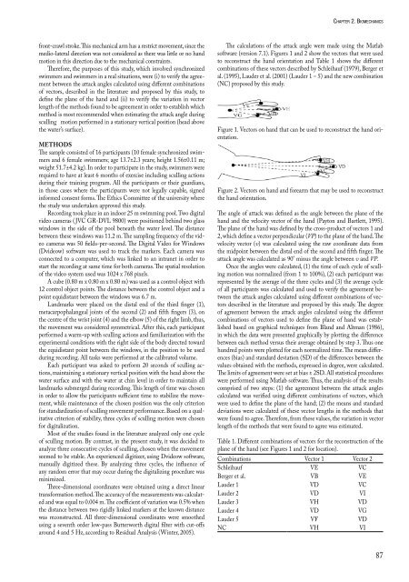
The calculations of the attack angle were made us<strong>in</strong>g the Matlab<br />
software (version 7.1). Figures 1 <strong>and</strong> 2 show the vectors that were used<br />
to reconstruct the h<strong>and</strong> orientation <strong>and</strong> Table 1 shows the different<br />
comb<strong>in</strong>ations of these vectors described by Schleihauf (1979), Berger et<br />
al. (1995), Lauder et al. (2001) (Lauder 1 – 5) <strong>and</strong> the new comb<strong>in</strong>ation<br />
(NC) proposed by this study.<br />
Figure 1. Vectors on h<strong>and</strong> that can be used to reconstruct the h<strong>and</strong> orientation.<br />
Figure 2. Vectors on h<strong>and</strong> <strong>and</strong> forearm that may be used to reconstruct<br />
the h<strong>and</strong> orientation.<br />
The angle of attack was def<strong>in</strong>ed as the angle between the plane of the<br />
h<strong>and</strong> <strong>and</strong> the velocity vector of the h<strong>and</strong> (Payton <strong>and</strong> Bartlett, 1995).<br />
The plane of the h<strong>and</strong> was def<strong>in</strong>ed by the cross-product of vectors 1 <strong>and</strong><br />
2, which def<strong>in</strong>e a vector perpendicular (VP) to the plane of the h<strong>and</strong>. The<br />
velocity vector (v) was calculated us<strong>in</strong>g the raw coord<strong>in</strong>ate data from<br />
the midpo<strong>in</strong>t between the distal end of the second <strong>and</strong> fifth f<strong>in</strong>ger. The<br />
attack angle was calculated as 90° m<strong>in</strong>us the angle between v <strong>and</strong> VP.<br />
Once the angles were calculated, (1) the time of each cycle of scull<strong>in</strong>g<br />
motion was normalized (from 1 to 100%), (2) each participant was<br />
represented by the average of the three cycles <strong>and</strong> (3) the average cycle<br />
of all participants was calculated <strong>and</strong> used to verify the agreement between<br />
the attack angles calculated us<strong>in</strong>g different comb<strong>in</strong>ations of vectors<br />
described <strong>in</strong> the literature <strong>and</strong> proposed by this study. The degree<br />
of agreement between the attack angles calculated us<strong>in</strong>g the different<br />
comb<strong>in</strong>ations of vectors used to def<strong>in</strong>e the plane of h<strong>and</strong> was established<br />
based on graphical techniques from Bl<strong>and</strong> <strong>and</strong> Altman (1986),<br />
<strong>in</strong> which the data were presented graphically by plott<strong>in</strong>g the difference<br />
between each method versus their average obta<strong>in</strong>ed by step 3. Thus one<br />
hundred po<strong>in</strong>ts were plotted for each normalized time. The mean differences<br />
(bias) <strong>and</strong> st<strong>and</strong>ard deviation (SD) of the differences between the<br />
values obta<strong>in</strong>ed with the methods, expressed <strong>in</strong> degree, were calculated.<br />
The limits of agreement were set at bias ± 2SD. All statistical procedures<br />
were performed us<strong>in</strong>g Matlab software. Thus, the analysis of the results<br />
comprised of two steps: (1) the agreement between the attack angles<br />
calculated was verified us<strong>in</strong>g different comb<strong>in</strong>ations of vectors, which<br />
were used to def<strong>in</strong>e the plane of the h<strong>and</strong>; (2) the means <strong>and</strong> st<strong>and</strong>ard<br />
deviations were calculated of these vector lengths <strong>in</strong> the methods that<br />
were found to agree. Therefore, from these values, the variation <strong>in</strong> vector<br />
length of the methods that were found to agree was estimated.<br />
Table 1. Different comb<strong>in</strong>ations of vectors for the reconstruction of the<br />
plane of the h<strong>and</strong> (see Figures 1 <strong>and</strong> 2 for location).<br />
Comb<strong>in</strong>ations Vector 1 Vector 2<br />
Schleihauf VE VC<br />
Berger et al. VB VE<br />
Lauder 1 VD VC<br />
Lauder 2 VD VI<br />
Lauder 3 VH VD<br />
Lauder 4 VD VG<br />
Lauder 5 VF VD<br />
NC VH VI<br />
87