

Controls, Start-Up, Operation, Service and ... - Climayoreo
Controls, Start-Up, Operation, Service and ... - Climayoreo
Controls, Start-Up, Operation, Service and ... - Climayoreo

You also want an ePaper? Increase the reach of your titles
YUMPU automatically turns print PDFs into web optimized ePapers that Google loves.
Table 100 — IGC Board Inputs <strong>and</strong> Outputs<br />
POINT NAME<br />
INPUTS<br />
POINT DESCRIPTION<br />
CONNECTOR<br />
PIN NO.<br />
RT 24 Volt Power Supply RT,C<br />
W Heat Dem<strong>and</strong> 2<br />
G Fan 3<br />
LS Limit Switch 7,8<br />
RS Rollout Switch 5,6<br />
SS Hall Effect Sensor 1,2,3<br />
CS Centrifugal Switch (Not Used) 9,10<br />
FS<br />
OUTPUTS<br />
Flame Sense FS<br />
CM Induced Draft Motor CM<br />
IFO Indoor Fan IFO<br />
R 24 Volt Power Output (Not Used) R<br />
SPARK Sparker —<br />
LED Display LED<br />
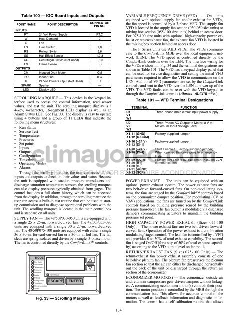
SCROLLING MARQUEE — This device is the keypad interface<br />
used to access the control information, read sensor<br />
values, <strong>and</strong> test the unit. The scrolling marquee display is a<br />
4-key, 4-character, 16-segment LED display as well as an<br />
Alarm Status LED. See Fig. 33. The display is easy to operate<br />
using 4 buttons <strong>and</strong> a group of 11 LEDs that indicate the<br />
following menu structures:<br />
• Run Status<br />
• <strong>Service</strong> Test<br />
• Temperatures<br />
• Pressures<br />
• Set points<br />
• Inputs<br />
• Outputs<br />
• Configuration<br />
• Timeclock<br />
• Operating Modes<br />
• Alarms<br />
Through the scrolling marquee, the user can access all the<br />
inputs <strong>and</strong> outputs to check on their values <strong>and</strong> status. Because<br />
the unit is equipped with suction pressure transducers <strong>and</strong><br />
discharge saturation temperature sensors, the scrolling marquee<br />
can also display pressures typically obtained from gages. The<br />
control includes a full alarm history, which can be accessed<br />
from the display. In addition, through the scrolling marquee the<br />
user can access a built-in test routine that can be used at startup<br />
commission <strong>and</strong> to diagnose operational problems with the<br />
unit. The scrolling marquee is located in the main control box<br />
<strong>and</strong> is st<strong>and</strong>ard on all units.<br />
SUPPLY FAN — The 48/50P030-050 units are equipped with<br />
a single 25 x 25-in. forward-curved fan. The 48/50P055-070<br />
units are equipped with a single 30 x 27-in. forward-curved<br />
fan. The 48/50P075-100 units are equipped with either a single<br />
36 x 30-in. forward-curved fan or a 36-in. airfoil fan. The fan<br />
sleds are spring isolated <strong>and</strong> driven by a single, 3-phase motor.<br />
The fan is controlled directly by the ComfortLink controls.<br />
MODE<br />
Run Status<br />
<strong>Service</strong> Test<br />
Temperature<br />
Pressures<br />
Setpoints<br />
Inputs<br />
Outputs<br />
Configuration<br />
Time Clock<br />
Operating Modes<br />
Alarms<br />
Alarm Status<br />
ESCAPE<br />
ENTER<br />
Fig. 33 — Scrolling Marquee<br />
134<br />
VARIABLE FREQUENCY DRIVE (VFD) — On units<br />
equipped with optional supply fan <strong>and</strong>/or exhaust fan VFDs,<br />
the fan speed is controlled by a 3-phase VFD. The supply fan<br />
VFD is located in the supply fan section (030-050 size units) or<br />
mixing box section (055-100 size units) behind an access door.<br />
For 075-100 size units with optional high-capacity power exhaust<br />
or return/exhaust fan, the exhaust fan VFD is located in<br />
the mixing box section behind an access door.<br />
The P Series units use ABB VFDs. The VFDs communicate<br />
to the ComfortLink MBB over the local equipment network<br />
(LEN). The VFD speed is controlled directly by the<br />
ComfortLink controls over the LEN. The interface wiring for<br />
the VFDs is shown in Fig. 34 <strong>and</strong> the terminal designations are<br />
shown in Table 101. The VFD has a keypad display panel that<br />
can be used for service diagnostics <strong>and</strong> setting the initial VFD<br />
parameters required to allow the VFD to communicate on the<br />
LEN. Additional VFD parameters are set by the ComfortLink<br />
controls, <strong>and</strong> sent to the VFD over the LEN at power up of the<br />
VFD. The VFD faults can be reset with the VFD keypad or<br />
through the ComfortLink controls (AlarmsR.CUR =Yes).<br />
Table 101 — VFD Terminal Designations<br />
TERMINAL FUNCTION<br />
U1 Three-phase main circuit input power supply<br />
V1<br />
W1<br />
U2 Three-Phase AC Output to Motor, 0 V to<br />
V2<br />
Maximum Input Voltage Level<br />
W2<br />
X1-11 (GND) Factory-supplied jumper<br />
X1-12 (D-COM)<br />
X1-10 (+24 V) Factory-supplied jumper<br />
X1-13 (DI-1)<br />
X1-10 (+24 V) <strong>Start</strong> Enable 1 (Factory-supplied jumper).<br />
X1-16 (DI-4) When opened the drive goes to emergency<br />
stop.<br />
X1-28 (SCR) Factory wired for local equipment network LEN<br />
X1-29 (B+) communication<br />
X1-30 (B-)<br />
X1-31 (AGND)<br />
X1-32 (SCR)<br />
POWER EXHAUST — The units can be equipped with an<br />
optional power exhaust system. The power exhaust fans are<br />
two belt-drive forward-curved fans. On non-modulating systems,<br />
the fans are staged by the ComfortLink controls based<br />
on the economizer damper position. For modulating (CV or<br />
VAV) applications, the fans are turned on by the ComfortLink<br />
controls based on building pressure sensed by the building<br />
pressure transducer. The fan output is modulated via discharge<br />
dampers communicating actuators to maintain the building<br />
pressure set point.<br />
HIGH CAPACITY POWER EXHAUST (Sizes 075-100<br />
Only) — The power exhaust fans are two belt-driven forwardcurved<br />
fans. <strong>Operation</strong> of the power exhaust is a combination<br />
modulating/staged control. The lead fan is controlled by a VFD<br />
<strong>and</strong> provides 0 to 50% of total exhaust capability. The second<br />
fan is staged On/Off (for a step of 50% of total exhaust capability)<br />
according to the VFD output level on fan no. 1.<br />
RETURN/EXHAUST FAN (Sizes 075-100 Only) — The<br />
return/exhaust fan power exhaust assembly consists of one<br />
belt-drive plenum fan. The plenum fan pressurizes the plenum<br />
fan section so that the air can either be discharged horizontally<br />
out the back of the unit or discharged through the return air<br />
section of the economizer.<br />
ECONOMIZER MOTOR(S) — The economizer outside air<br />
<strong>and</strong> return air dampers are gear-driven dampers without linkages.<br />
A communicating economizer motor(s) controls their position.<br />
The motor position is controlled by the MBB through the<br />
communication bus. This allows for accurate control of the<br />
motors as well as feedback information <strong>and</strong> diagnostics information.<br />
The control has a self-calibration routine that allows


