

Controls, Start-Up, Operation, Service and ... - Climayoreo
Controls, Start-Up, Operation, Service and ... - Climayoreo
Controls, Start-Up, Operation, Service and ... - Climayoreo

You also want an ePaper? Increase the reach of your titles
YUMPU automatically turns print PDFs into web optimized ePapers that Google loves.
LIMIT<br />
SWITCH<br />
NO. 1<br />
FLUE<br />
OUTLET<br />
SECTION 1<br />
GAS VALVE<br />
LIMIT<br />
SWITCH<br />
NO. 2<br />
Fig. 42 — Gas Section Detail, Sizes 055-100 —<br />
High Heat<br />
Fig. 43 — Burner Section Detail<br />
FLUE<br />
OUTLET<br />
SECTION 2<br />
GAS VALVE<br />
FLUE<br />
OUTLET<br />
SECTION 3<br />
GAS VALVE<br />
To inspect blower wheel, remove heat exchanger access<br />
panel. Shine a flashlight into opening to inspect wheel. If cleaning<br />
is required, remove motor <strong>and</strong> wheel assembly by removing<br />
screws holding motor mounting plate to top of combustion<br />
fan housing (Fig. 45). The motor <strong>and</strong> wheel assembly will slide<br />
up <strong>and</strong> out of the fan housing. Remove the blower wheel from<br />
the motor shaft <strong>and</strong> clean with a detergent or solvent. Replace<br />
motor <strong>and</strong> wheel assembly.<br />
ECONOMIZER DAMPER MOTOR(S) — On units so<br />
equipped, the economizer motor(s) is located in the mixing<br />
box section. Access to it is through the door labeled FILTER<br />
SECTION.<br />
140<br />
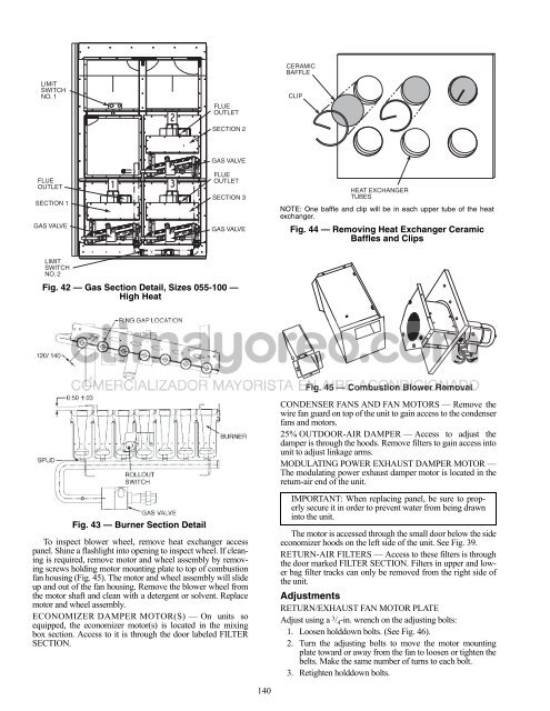
CERAMIC<br />
BAFFLE<br />
CLIP<br />
HEAT EXCHANGER<br />
TUBES<br />
NOTE: One baffle <strong>and</strong> clip will be in each upper tube of the heat<br />
exchanger.<br />
Fig. 44 — Removing Heat Exchanger Ceramic<br />
Baffles <strong>and</strong> Clips<br />
Fig. 45 — Combustion Blower Removal<br />
CONDENSER FANS AND FAN MOTORS — Remove the<br />
wire fan guard on top of the unit to gain access to the condenser<br />
fans <strong>and</strong> motors.<br />
25% OUTDOOR-AIR DAMPER — Access to adjust the<br />
damper is through the hoods. Remove filters to gain access into<br />
unit to adjust linkage arms.<br />
MODULATING POWER EXHAUST DAMPER MOTOR —<br />
The modulating power exhaust damper motor is located in the<br />
return-air end of the unit.<br />
IMPORTANT: When replacing panel, be sure to properly<br />
secure it in order to prevent water from being drawn<br />
into the unit.<br />
The motor is accessed through the small door below the side<br />
economizer hoods on the left side of the unit. See Fig. 39.<br />
RETURN-AIR FILTERS — Access to these filters is through<br />
the door marked FILTER SECTION. Filters in upper <strong>and</strong> lower<br />
bag filter tracks can only be removed from the right side of<br />
the unit.<br />
Adjustments<br />
RETURN/EXHAUST FAN MOTOR PLATE<br />
Adjust using a 3 / 4-in. wrench on the adjusting bolts:<br />
1. Loosen holddown bolts. (See Fig. 46).<br />
2. Turn the adjusting bolts to move the motor mounting<br />
plate toward or away from the fan to loosen or tighten the<br />
belts. Make the same number of turns to each bolt.<br />
3. Retighten holddown bolts.


