

Controls, Start-Up, Operation, Service and ... - Climayoreo
Controls, Start-Up, Operation, Service and ... - Climayoreo
Controls, Start-Up, Operation, Service and ... - Climayoreo

Create successful ePaper yourself
Turn your PDF publications into a flip-book with our unique Google optimized e-Paper software.
set point (ConfigurationIAQAQ.SP menu) <strong>and</strong> the supply<br />
fan is on, the economizer minimum vent position (ConfigurationIAQDCV.CEC.MN)<br />
is overridden <strong>and</strong> the<br />
damper is moved to the IQ.P.O configuration. When the DAQ<br />
falls below the DAQ.L set point (ConfigurationIAQAQ.SP<br />
menu), the economizer damper is moved<br />
back to the minimum vent position (EC.MN).<br />
NOTE: Configuration OAQ.U is used in the calculation of the<br />
trip point for override <strong>and</strong> can be found under Configuration<br />
IAQAQ.SP.<br />
IQ.A.C = 3 (4 to 20 mA Damper Control) — This configuration<br />
will provide full 4 to 20 mA remotely controlled analog input<br />
for economizer minimum damper position. The 4 to 20 mA<br />
signal is connected to terminals TB201-8 <strong>and</strong> TB201-7. The<br />
input is processed as 4 mA = 0% <strong>and</strong> 20 mA = 100%, thereby<br />
giving complete range control of the effective minimum<br />
position.<br />
The economizer sequences can be disabled by unpluging<br />
the enthalpy switch input <strong>and</strong> not enabling any other economizer<br />
changeover sequence at ConfigurationECONE.SEL.<br />
Complete control of the economizer<br />
damper position is then possible by using a 4 to 20 mA economizer<br />
minimum position control or a 0 to 10 kilo-ohm 0 to<br />
100% economizer minimum position control via configuration<br />
decisions at ConfigurationIAQIQ.A.C.<br />
To disable the st<strong>and</strong>ard enthalpy control input function,<br />
unplug the enthalpy switch <strong>and</strong> provide a jumper from TB201-<br />
6 to TB201-5 (see wiring diagrams in Major System Components<br />
section on page 116).<br />
IQ.A.C = 4 (10 Kohm Potentiometer Damper Control) —<br />
This configuration will provide input for a 10 kilo-ohm linear<br />
potentiometer that acts as a remotely controlled analog input<br />
for economizer minimum damper position. The input is processed<br />
as 0 ohms = 0% <strong>and</strong> 10,000 ohms = 100%, thereby giving<br />
complete range control of the effective minimum position.<br />
NOTE: For complete economizer control, the user can make<br />
the economizer inactive by unplugging the enthalpy switch<br />
connection.<br />
CONTROLS OPERATION<br />
Modes — The ComfortLink controls operate under a<br />
hierarchy of comm<strong>and</strong> structure as defined by three essential<br />
elements: the System mode, the HVAC mode <strong>and</strong> the Control<br />
mode. The System mode is the top level mode that defines three<br />
essential states for the control system: OFF, RUN <strong>and</strong> TEST.<br />
The HVAC mode is the functional level underneath the<br />
System mode which further defines the operation of the<br />
control.<br />
The Control mode is essentially the control type of the unit<br />
(ConfigurationUNITC.TYP). This defines from where<br />
the control looks to establish a cooling or heating mode.<br />
Furthermore, there are a number of modes which operate<br />
concurrently when the unit is running. The operating modes of<br />
the control are located at the local displays under Operating<br />
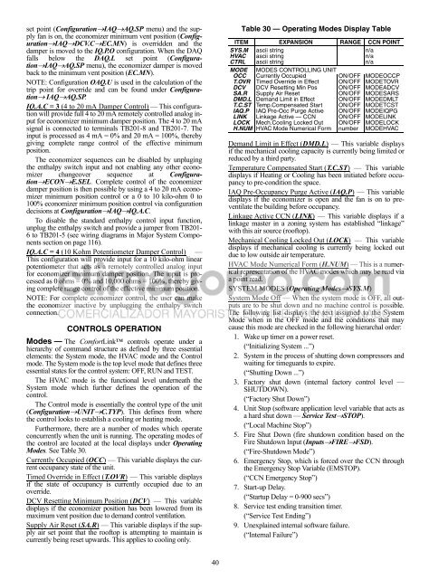
Modes. See Table 30.<br />
Currently Occupied (OCC) — This variable displays the current<br />
occupancy state of the unit.<br />
Timed Override in Effect (T.OVR) — This variable displays<br />
if the state of occupancy is currently occupied due to an<br />
override.<br />
DCV Resetting Minimum Position (DCV) — This variable<br />
displays if the economizer position has been lowered from its<br />
maximum vent position due to dem<strong>and</strong> control ventilation.<br />
Supply Air Reset (SA.R) — This variable displays if the supply<br />
air set point that the rooftop is attempting to maintain is<br />
currently being reset upwards. This applies to cooling only.<br />
40<br />
Table 30 — Operating Modes Display Table<br />
ITEM EXPANSION RANGE CCN POINT<br />
SYS.M ascii string n/a<br />
HVAC ascii string n/a<br />
CTRL ascii string n/a<br />
MODE MODES CONTROLLING UNIT<br />
OCC Currently Occupied ON/OFF MODEOCCP<br />
T.OVR Timed Override in Effect ON/OFF MODETOVR<br />
DCV DCV Resetting Min Pos ON/OFF MODEADCV<br />
SA.R Supply Air Reset ON/OFF MODESARS<br />
DMD.L Dem<strong>and</strong> Limit in Effect ON/OFF MODEDMLT<br />
T.C.ST Temp.Compensated <strong>Start</strong> ON/OFF MODETCST<br />
IAQ.P IAQ Pre-Occ Purge Active ON/OFF MODEIQPG<br />
LINK Linkage Active — CCN ON/OFF MODELINK<br />
LOCK Mech.Cooling Locked Out ON/OFF MODELOCK<br />
H.NUM HVAC Mode Numerical Form number MODEHVAC<br />
Dem<strong>and</strong> Limit in Effect (DMD.L) — This variable displays<br />
if the mechanical cooling capacity is currently being limited or<br />
reduced by a third party.<br />
Temperature Compensated <strong>Start</strong> (T.C.ST) — This variable<br />
displays if Heating or Cooling has been initiated before occupancy<br />
to pre-condition the space.<br />
IAQ Pre-Occupancy Purge Active (IAQ.P) — This variable<br />
displays if the economizer is open <strong>and</strong> the fan is on to preventilate<br />
the building before occupancy.<br />
Linkage Active CCN (LINK) — This variable displays if a<br />
linkage master in a zoning system has established “linkage”<br />
with this air source (rooftop).<br />
Mechanical Cooling Locked Out (LOCK) — This variable<br />
displays if mechanical cooling is currently being locked out<br />
due to low outside air temperature.<br />
HVAC Mode Numerical Form (H.NUM) — This is a numerical<br />
representation of the HVAC modes which may be read via<br />
a point read.<br />
SYSTEM MODES (Operating ModesSYS.M)<br />
System Mode Off — When the system mode is OFF, all outputs<br />
are to be shut down <strong>and</strong> no machine control is possible.<br />
The following list displays the text assigned to the System<br />
Mode when in the OFF mode <strong>and</strong> the conditions that may<br />
cause this mode are checked in the following hierarchal order:<br />
1. Wake up timer on a power reset.<br />
(“Initializing System ...”)<br />
2. System in the process of shutting down compressors <strong>and</strong><br />
waiting for timeguards to expire.<br />
(“Shutting Down ...”)<br />
3. Factory shut down (internal factory control level —<br />
SHUTDOWN).<br />
(“Factory Shut Down”)<br />
4. Unit Stop (software application level variable that acts as<br />
a hard shut down — <strong>Service</strong> TestSTOP).<br />
(“Local Machine Stop”)<br />
5. Fire Shut Down (fire shutdown condition based on the<br />
Fire Shutdown Input (InputsFIREFSD).<br />
(“Fire-Shutdown Mode”)<br />
6. Emergency Stop, which is forced over the CCN through<br />
the Emergency Stop Variable (EMSTOP).<br />
(“CCN Emergency Stop”)<br />
7. <strong>Start</strong>-up Delay.<br />
(“<strong>Start</strong>up Delay = 0-900 secs”)<br />
8. <strong>Service</strong> test ending transition timer.<br />
(“<strong>Service</strong> Test Ending”)<br />
9. Unexplained internal software failure.<br />
(“Internal Failure”)


