

Controls, Start-Up, Operation, Service and ... - Climayoreo
Controls, Start-Up, Operation, Service and ... - Climayoreo
Controls, Start-Up, Operation, Service and ... - Climayoreo

Create successful ePaper yourself
Turn your PDF publications into a flip-book with our unique Google optimized e-Paper software.
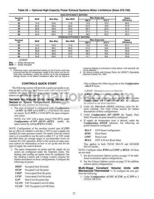
Table 28 — Optional High-Capacity Power Exhaust Systems Motor Limitations (Sizes 075-100)<br />
HIGH-EFFICIENCY MOTORS<br />
Nominal<br />
HP<br />
BkW Max Bhp Max BkW<br />
Max Amps (ea)<br />
460 V 575 V<br />
Rated<br />
Efficiency<br />
20 14.9 23.6 17.6 14.6 12.0 89.5<br />
30 22.4 36.0 26.9 21.9 19.0 91.0<br />
40 29.8 46.8 34.9 28.7 23.0 91.0<br />
50 37.3 58.8 43.9 37.4 31.0 91.7<br />
60 44.8 69.0 51.5 48.0 36.3 92.4<br />
PREMIUM-EFFICIENCY MOTORS<br />
Nominal<br />
HP<br />
BkW Max Bhp Max BkW<br />
Max Amps (ea)<br />
460 V 575 V<br />
Rated<br />
Efficiency<br />
20 14.9 23.6 17.6 15.0 N/A 91.7<br />
30 22.4 36.0 26.9 21.9 N/A 93.0<br />
40 29.8 46.8 34.9 28.7 N/A 93.6<br />
50 37.3 58.8 43.9 36.3 N/A 93.6<br />
60 44.8 69.0 51.5 41.7 N/A 93.6<br />
Bhp —<br />
LEGEND<br />
Brake Horsepower<br />
BkW — Brake Kilowatts<br />
NOTES:<br />
1. Extensive motor <strong>and</strong> electrical testing on the Carrier units has<br />
ensured that the full horsepower range of the motor can be utilized<br />
with confidence. Using fan motors up to the horsepower<br />
ratings shown in the Motor Limitations table will not result in<br />
CONTROLS QUICK START<br />
The following section will provide a quick user guide to setting<br />
up <strong>and</strong> configuring the P Series units with ComfortLink<br />
controls. See Basic Control Usage section on page 3 for information<br />
on operating the control.<br />
Variable Air Volume Units Using Return Air<br />
Sensor or Space Temperature Sensor — To<br />
configure the unit, perform the following:<br />
1. The type of control is configured under Configuration<br />
UNITC.TYP. Set C.TYP to 1 (VAV-RAT) for return<br />
air sensor. Set C.TYP to 2 (VAV-SPT) for space temperature<br />
sensor.<br />
NOTE: For VAV with a space sensor (VAV-SPT), under<br />
ConfigurationUNITSENSSPT.S, enable the<br />
space sensor by setting SPT.S to ENBL.<br />
NOTE: Configuration of the machine control type (C.TYP)<br />
has no effect on whether a unit has a VFD or just a supply fan<br />
installed for static pressure control. No matter what the control<br />
type is, it is possible to run the unit in either CV or VAV mode<br />
provided there are enough stages to accommodate lower air<br />
volumes for VAV operation. Refer to the section on static pressure<br />
control for information on how to set up the unit for the<br />
type of supply fan control desired.<br />
2. The space temperature set points <strong>and</strong> the supply air set<br />
points are configured under the Setpoints menu. The<br />
heating <strong>and</strong> cooling set points must be configured. See<br />
the Heating Control <strong>and</strong> Cooling Control sections for<br />
further description on these configurations. Configure the<br />
following set points:<br />
OHSP Occupied Heat Set point<br />
OCSP Occupied Cool Set point<br />
UHSP Unoccupied Heat Set point<br />
UCSP Unoccupied Cool Set point<br />
GAP Heat-Cool Set point Gap<br />
V.C.ON VAV Occupied Cool On Delta<br />
V.C.OF VAV Occupied Cool Off Delta<br />
32<br />
nuisance tripping or premature motor failure. Unit warranty will<br />
not be affected.<br />
2. All motors comply with Energy Policy Act (EPACT) St<strong>and</strong>ards<br />
effective October 24, 1997.<br />
Also configure the following points in the Configuration<br />
D.LV.T menu:<br />
L.H.ON Dem<strong>and</strong> Level Low Heat On<br />
L.H.OF Dem<strong>and</strong> Level Low Heat Off<br />
3. To program time schedules, make sure SCH.N=1 under<br />
ConfigurationCCNSC.OVSCH.N to configure<br />
the control to use local schedules.<br />
4. Under the TimeclockSCH.L submenu, enter the desired<br />
schedule. See Time Clock section for further<br />
descriptions of these configurations.<br />
5. Under ConfigurationSPSP.SP, the Supply Duct<br />
Static Pressure set point should be configured.<br />
6. If supply air temperature reset is desired, under the<br />
ConfigurationEDT.R submenu, the following set<br />
points should be configured:<br />
RS.CF EDT Reset Configuration<br />
RTIO Reset Ratio<br />
LIMT Reset Limit<br />
RES.S EDT 4-20 mA Reset Input<br />
This applies to both TSTAT MULTI <strong>and</strong> SENSOR<br />
MULTI modes.<br />
NOTE: Configure either RTIO <strong>and</strong> LIMT or RES.S. All three<br />
are not used.<br />
7. See the Economizer Options section on page 33 for additional<br />
economizer option configurations.<br />
8. See the Exhaust Options section on page 33 for addition<br />
exhaust option configurations.<br />
Multi-Stage Constant Volume Units with<br />
Mechanical Thermostat — To configure the unit, perform<br />
the following:<br />
1. Under ConfigurationUNITC.TYP, set C.TYP to 3<br />
(TSTAT MULTI).


