Controls, Start-Up, Operation, Service and ... - Climayoreo
Controls, Start-Up, Operation, Service and ... - Climayoreo
Controls, Start-Up, Operation, Service and ... - Climayoreo
You also want an ePaper? Increase the reach of your titles
YUMPU automatically turns print PDFs into web optimized ePapers that Google loves.
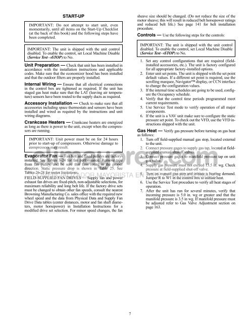
START-UP<br />
IMPORTANT: Do not attempt to start unit, even<br />
momentarily, until all items on the <strong>Start</strong>-<strong>Up</strong> Checklist<br />
(at the back of this book) <strong>and</strong> the following steps have<br />
been completed.<br />
IMPORTANT: The unit is shipped with the unit control<br />
disabled. To enable the control, set Local Machine Disable<br />
(<strong>Service</strong> TestSTOP) to No.<br />
Unit Preparation — Check that unit has been installed in<br />
accordance with the installation instructions <strong>and</strong> applicable<br />
codes. Make sure that the economizer hood has been installed<br />
<strong>and</strong> that the outdoor filters are properly installed.<br />
Internal Wiring — Ensure that all electrical connections<br />
in the control box are tightened as required. If the unit has<br />
staged gas heat make sure that the LAT (leaving air temperature)<br />
sensors have been routed to the supply ducts as required.<br />
Accessory Installation — Check to make sure that all<br />
accessories including space thermostats <strong>and</strong> sensors have been<br />
installed <strong>and</strong> wired as required by the instructions <strong>and</strong> unit<br />
wiring diagrams.<br />
Crankcase Heaters — Crankcase heaters are energized<br />
as long as there is power to the unit, except when the compressors<br />
are running.<br />
IMPORTANT: Unit power must be on for 24 hours<br />
prior to start-up of compressors. Otherwise damage to<br />
compressors may result.<br />
Evaporator Fan — Fan belt <strong>and</strong> fixed pulleys are factoryinstalled.<br />
See Tables 3-24 for fan performance. Remove tape<br />
from fan pulley, <strong>and</strong> be sure that fans rotate in the proper<br />
direction. Static pressure drop is shown in Table 25. See<br />
Tables 26-28 for motor limitations.<br />
FIELD-SUPPLIED FAN DRIVES — Supply fan <strong>and</strong> power<br />
exhaust fan drives are fixed-pitch, non-adjustable selections, for<br />
maximum reliability <strong>and</strong> long belt life. If the factory drive sets<br />
must be changed to obtain other fan speeds, consult the nearest<br />
Browning Manufacturing Co. sales office with the required new<br />
wheel speed <strong>and</strong> the data from Physical Data <strong>and</strong> Supply Fan<br />
Drive Data tables (center distances, motor <strong>and</strong> fan shaft diameters,<br />
motor horsepower) in Installation Instructions for a<br />
modified drive set selection. For minor speed changes, the fan<br />
7<br />
sheave size should be changed. (Do not reduce the size of the<br />
motor sheave; this will result in reduced belt horsepower ratings<br />
<strong>and</strong> reduced belt life.) See page 141 for belt installation<br />
procedure.<br />
<strong>Controls</strong> — Use the following steps for the controls:<br />
IMPORTANT: The unit is shipped with the unit control<br />
disabled. To enable the control, set Local Machine Disable<br />
(<strong>Service</strong> TestSTOP) to No.<br />
1. Set any control configurations that are required (fieldinstalled<br />
accessories, etc.). The unit is factory configured<br />
for all appropriate factory-installed options.<br />
2. Enter unit set points. The unit is shipped with the set point<br />
default values. If a different set point is required, use the<br />
scrolling marquee, Navigator display, or CCN interface<br />
to change the configuration values.<br />
3. If the internal time schedules are going to be used, configure<br />
the Occupancy schedule.<br />
4. Verify that the control time periods programmed meet<br />
current requirements.<br />
5. Use <strong>Service</strong> Test mode to verify operation of all major<br />
components.<br />
6. If the unit is a VAV unit make sure to configure the static<br />
pressure set point. To check out the VFD, use the VFD instructions<br />
shipped with the unit.<br />
Gas Heat — Verify gas pressure before turning on gas heat<br />
as follows:<br />
1. Turn off field-supplied manual gas stop, located external<br />
to the unit.<br />
2. Connect pressure gages to supply gas tap, located at fieldsupplied<br />
manual shutoff valves.<br />
3. Connect pressure gages to manifold pressure tap on unit<br />
gas valve.<br />
4. Supply gas pressure must not exceed 13.5 in. wg. Check<br />
pressure at field-supplied shut-off valve.<br />
5. Turn on manual gas stop <strong>and</strong> initiate a heating dem<strong>and</strong>.<br />
Jumper R to W1 in the control box to initiate heat.<br />
6. Use the <strong>Service</strong> Test procedure to verify all heat stages of<br />
operation.<br />
7. After the unit has run for several minutes, verify that<br />
incoming pressure is 5.0 in. wg or greater <strong>and</strong> that the<br />
manifold pressure is 3.5 in wg. If manifold pressure must<br />
be adjusted refer to Gas Valve Adjustment section on<br />
page 163.


