Concrete Plant + Precast Technology Betonwerk ... - BFT International
Concrete Plant + Precast Technology Betonwerk ... - BFT International
Concrete Plant + Precast Technology Betonwerk ... - BFT International

Sie wollen auch ein ePaper? Erhöhen Sie die Reichweite Ihrer Titel.
YUMPU macht aus Druck-PDFs automatisch weboptimierte ePaper, die Google liebt.
54. BetonTage Kongressunterlagen |<br />
specifi ed value, in some bays even to 68%. The lower value<br />
applies as it is not possible to comply with diff erent values<br />
for each bay during cargo handling operations. This results<br />
in a reduction of the permissible fl oor loading to approx.<br />
10 kN/m².<br />
Measurements also show that the support reinforcement<br />
placed at the top was turned by 90 degrees in one of<br />
the concreting sections compared to the position in the<br />
two other sections, which means that the main reinforcement<br />
was inserted as the second layer in this area.<br />
Remedial work<br />
Remedial work on the upper surface of the fl oor, such as<br />
the placement of an additional reinforced concrete topping,<br />
is not an option for technical and operational reasons.<br />
For obvious structural reasons, the amount of reinforcement<br />
that is missing on the upper side cannot be<br />
compensated at the bottom of the fl oor slab. On the parking<br />
level, clearance heights in accordance with relevant<br />
German regulations (GVO) must be adhered to.<br />
The owner thus claims the construction of additional<br />
fl oor space to the extent necessary to compensate for the<br />
calculated service load reduction. In the case at hand, this<br />
would be achieved by the construction of a new industrial<br />
building with a fl oor space of approx. 900 m².<br />
Technical responsibility<br />
The obvious assumption that the excessively high top concrete<br />
cover is exclusively due to a defect in execution is<br />
actually an incorrect generalization. The reinforcement<br />
plan does not include any detail that specifi es which layer<br />
of the support reinforcement to place as the top layer. The<br />
reinforcement of all three sections was accepted by the<br />
structural engineer prior to concrete placement. He was<br />
able to visually inspect and recognize its positioning. He<br />
was able to estimate the thickness of the top concrete cover<br />
on the basis of a visual inspection, or to verify it by very<br />
simple means. Moreover, the fact that additional mesh reinforcement<br />
was specifi ed in the reinforcement plan resulted<br />
in overlaps in the support area, which required the<br />
use of spacers for the top reinforcement layer that were<br />
lower than specifi ed in the plan. In this respect, it was not<br />
possible to insert the reinforcement according to plan.<br />
In addition, the crack widths in the tensile bending<br />
zone are larger than in the approximate calculation because<br />
imposed stresses or strains, such as those caused by<br />
concrete drying shrinkage, were not taken into account<br />
for the purpose of the calculation.<br />
<strong>BFT</strong> 02/2010<br />
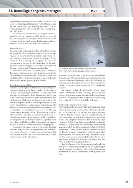
Fig. 2 Typical cracking pattern along the column axes.<br />
Abb. 2 Typische Rissbildung längs der Stützenachsen.<br />
Podium 8<br />
scheidet aus technischen, aber auch aus betrieblichen<br />
Gründen aus. Unterseitig kann aus naheliegenden statischen<br />
Gründen die oberseitig rechnerisch fehlende Bewehrung<br />
nicht kompensiert werden. Die Durchfahrtshöhen<br />
im Parkgeschoss müssen nach GVO eingehalten<br />
werden.<br />
Der Bauherr verlangt deshalb die Herstellung zusätzlicher<br />
Hallenfl äche in dem Umfang, der zur rechnerischen<br />
Kompensation der Nutzlastminderung erforderlich<br />
wird. Im gegebenen Fall würde dies Neuerrichtung<br />
einer Halle mit ca. 900 m² Nutzfl äche bedeuten.<br />
Technische Verantwortlichkeit<br />
Die naheliegende Annahme, dass die unzulässig hohe<br />
obere Betondeckung ausschließlich Ausführungsfehler<br />
sei, ist so pauschal nicht richtig. Im Bewehrungsplan<br />
fehlt die Angabe, welche Lage der Stützbewehrung als<br />
obere zu verlegen ist. Die Bewehrung aller drei Abschnitte<br />
wurde vom Tragwerksplaner vor dem Betonieren abgenommen.<br />
Er hat deren Lage augenscheinlich erkennen<br />
können. Er konnte die Größe der oberen Betondeckung<br />
augenscheinlich abschätzen oder mit einfachsten Mitteln<br />
überprüfen. Zudem ergaben sich im Stützbereich durch<br />
im Bewehrungsplan vorgegebene Mattenzulagen Übergreifungsstöße,<br />
die die Verwendung niedrigerer als der<br />
im Plan ausgewiesenen Abstandhalterböcke für die obere<br />
Bewehrung erforderlich machten – insoweit war dies<br />
nicht nach Bewehrungsplan ausführbar.<br />
Die Rissbreiten in der Biegezugzone sind auch deshalb<br />
größer als rechnerisch abgeschätzt, weil Spannungen<br />
bzw. Dehnungen aus Zwang, z. B. aus dem Trocknungsschwinden<br />
des Betons, rechnerisch nicht angesetzt wurden.<br />
135