Concrete Plant + Precast Technology Betonwerk ... - BFT International
Concrete Plant + Precast Technology Betonwerk ... - BFT International
Concrete Plant + Precast Technology Betonwerk ... - BFT International

Erfolgreiche ePaper selbst erstellen
Machen Sie aus Ihren PDF Publikationen ein blätterbares Flipbook mit unserer einzigartigen Google optimierten e-Paper Software.
180<br />
Panel 11<br />
spacing of the wrapping amounting to 50 mm across the<br />
entire pipe length for starter pipes and intermediate pressing<br />
stations.<br />
The trend to produce larger jacking pipes remaining in<br />
the formwork while hardening has led to the increased use<br />
of a chamber for the pipe connection. This prevents slippage<br />
of the seal during steering movements and enables<br />
higher water pressure due to the use of a round-shaped<br />
sealing ring. In addition, pipes hardened in the formwork<br />
do not only have a smoother surface than machine pipes<br />
but also provide a higher dimensional accuracy.<br />
Steel guide rings (also made of stainless or weatherresistant<br />
steel grades) must be fi xed appropriately and secured<br />
against penetration of surrounding water and humidity.<br />
A tried and tested solution is to fi x such rings by<br />
bolted connections or welded-on wall brackets, complemented<br />
by fully welded T squares. The length of the steel<br />
guide ring must be adjusted to anticipated steering movements.<br />
Consideration of the pressure transfer ring<br />
for steering and curved jacking<br />
In the future, the pressure transfer ring will be taken into<br />
account as an important component. Comprehensive<br />
tests have shown that rings made of wood products such<br />
as chipboard and OSB retain a residual degree of elasticity<br />
for a longer period and can accommodate angles in the<br />
case of frequent loading. In addition, the properties of<br />
these materials are more uniform than those of softwood.<br />
Due to the more elastic edge areas, a double-layer pressure<br />
transfer ring is more favorable than a single-layer<br />
ring when comparing identical thicknesses.<br />
It is also crucial that the pressure transfer ring is positioned<br />
appropriately. According to analyses carried out,<br />
edge distances that are too large are disadvantageous because<br />
they increase the tendency of gap formation at the<br />
pipe end face. The use of integrated secondary seals<br />
(IGLU) results in signifi cantly lower, permissible jacking<br />
forces.<br />
Preloading, for example caused by steering movements,<br />
must be accounted for at a ratio of least 30% of the<br />
maximum load. This value must be increased to up to<br />
87% in the case of several consecutive curves.<br />
Apart from the conventional load transfer using wood<br />
products, one of the new developments is the hydraulic<br />
joint formed by partially fi lled tubes. This type of joint ensures<br />
a more uniform load transfer also in curves and<br />
bends and thus enables narrower radii or greater pipe<br />
lengths. Although a number of pipeline projects have<br />
been successfully completed already, there are still some<br />
open questions with regard to the eff ects and implications<br />
of this method. Due to its considerably higher cost, this<br />
method is mainly used for special pipeline routes.<br />
Jacking beyond unconsolidated soil<br />
The previously applicable offi cial calculation methods<br />
only covered pipe jacking in unconsolidated soil. For jacking<br />
in rock or in the transition zone between rock and unconsolidated<br />
soil, a reduced angle of support, the degree<br />
of rock fragmentation or a vault action need to be considered<br />
depending on the hardness of the soil and the working<br />
method. The new version of A 161 contains proposals<br />
as to the calculation method to be applied, which needs to<br />
be coordinated with the geotechnical expert.<br />
| Proceedings 54 th BetonTage<br />
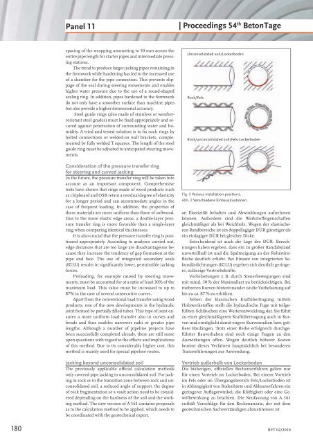
Unconsolidated soil/Lockerboden<br />
Rock/Fels<br />
Rock/unconsolidated soil/Fels-Lockerboden<br />
Fig. 2 Various installation positions.<br />
Abb. 2 Verschiedene Einbausituationen.<br />
an Elastizität behalten und Abwinklungen aufnehmen<br />
können. Außerdem sind die Werkstoff eigenschaften<br />
gleichmäßiger als bei Weichholz. Wegen der elastischeren<br />
Randbereiche ist ein doppellagiger DÜR günstiger als<br />
ein einlagiger DÜR bei gleicher Dicke.<br />
Entscheidend ist auch die Lage des DÜR. Berechnungen<br />
haben ergeben, dass ein zu großer Randabstand<br />
unvorteilhaft ist und die Spaltneigung an der Rohrstirnfl<br />
äche deutlich erhöht. Bei Einsatz von integrierten Sekundärdichtungen<br />
(IGLU) ergeben sich deutlich geringere,<br />
zulässige Vortriebskräfte.<br />
Vorbelastungen z. B. durch Steuerbewegungen sind<br />
mit mind. 30 % der Maximallast zu berücksichtigen. Bei<br />
mehreren Kurven hintereinander ist die Vorbelastung auf<br />
bis zu ca. 87 % zu erhöhen.<br />
Neben der klassischen Kraftübertragung mittels<br />
Holzwerkstoff en stellt die hydraulische Fuge mit teilgefüllten<br />
Schläuchen eine Weiterentwicklung dar. Sie führt<br />
zu einer gleichmäßigeren Kraftübertragung auch in Kurven<br />
und ermöglicht damit engere Kurvenradien bzw. größere<br />
Baulängen. Trotz einer Reihe erfolgreich durchgeführter<br />
Bauvorhaben sind noch einige Fragen zu den<br />
Auswirkungen off en. Wegen deutlich höherer Kosten<br />
kommt dieses Verfahren hauptsächlich bei besonderen<br />
Trassenführungen zur Anwendung.<br />
Vortrieb außerhalb von Lockerboden<br />
Die bisherigen, offi ziellen Rechenverfahren galten nur<br />
für einen Vortrieb im Lockerboden. Bei einem Vortrieb<br />
im Fels oder im Übergangsbereich Fels/Lockerboden ist<br />
in Abhängigkeit von Bodenhärte und Abbauverfahren ein<br />
geringerer Aufl agerwinkel, die Klüftigkeit oder eine Gewölbewirkung<br />
zu beachten. Die Neufassung von A 161<br />
enthält Vorschläge für den Rechenansatz, der mit dem<br />
geotechnischen Sachverständigen abzustimmen ist.<br />
<strong>BFT</strong> 02/2010