Concrete Plant + Precast Technology Betonwerk ... - BFT International
Concrete Plant + Precast Technology Betonwerk ... - BFT International
Concrete Plant + Precast Technology Betonwerk ... - BFT International

Sie wollen auch ein ePaper? Erhöhen Sie die Reichweite Ihrer Titel.
YUMPU macht aus Druck-PDFs automatisch weboptimierte ePaper, die Google liebt.
156<br />
Panel 10<br />
C 30/37, slab thickness 30 cm, double-layer reinforcement,<br />
concentric stress due to hydration heat, c = 50 mm,<br />
nom<br />
w = 0.2 mm<br />
k<br />
Reinforcing steel Combined reinforcement<br />
Rebars Ø12 mm – 110 mm Mesh Q 524 +<br />
post-cracking tensile strength<br />
1.0 N/mm²<br />
Table 1 Comparison of combined reinforcement with<br />
a conventional solution.<br />
thumb, the use of high-performance steel-fi ber reinforced<br />
concretes may result in a reduction in the minimum reinforcement<br />
required to ensure serviceability by up to 50%.<br />
The example shown in Table 1 was chosen to highlight this<br />
eff ect. For the purpose of verifying structural strength, however,<br />
the fi ber ratio is considerably lower in most cases.<br />
This means that the integration of combined reinforcement<br />
is useful whenever the required minimum reinforcement<br />
is the limiting factor, at least in larger areas<br />
of the element. If the reduced minimum reinforcement is<br />
taken into account in the subsequent planning and design<br />
process, combined with the selection of a production<br />
method tailored to this situation, this simple step alone<br />
can open up a signifi cant saving potential. The following<br />
examples should illustrate this principle:<br />
Example I<br />
A non-load bearing foundation slab specifi ed in compliance<br />
with the provisions of the Wasserhaushaltsgesetz<br />
(German Water Management Act) required a verifi ed<br />
crack width limitation in order to apply a sealing compound<br />
(Fig. 1). Due to the proposed design, which included<br />
combined reinforcement, the lower mesh that would<br />
have formed part of the double-layer reinforcement was<br />
no longer necessary. As a result, the upper mesh reinforcement<br />
that was still to be included could be inserted as<br />
part of the construction process. Additional waiting periods<br />
otherwise required to insert the reinforcement could<br />
be avoided. The steel-fi ber reinforced concrete could be<br />
unloaded from the truck mixers directly at the point of<br />
placement, which eliminated the need for the use of a concrete<br />
pump. In addition, the laying of the mesh reinforcement<br />
in parallel to construction progress enabled the use<br />
of semi-automatic installation systems (“laser screed”,<br />
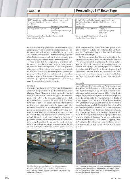
Fig. 1 Reinforcement installation in line with construction<br />
progress enabled by the use of combined reinforcement.<br />
Abb. 1 Baubegleitender Bewehrungseinbau durch Verwendung<br />
von Kombibewehrung.<br />
| Proceedings 54 th BetonTage<br />
C 30/37, Plattendicke 30 cm, doppellagige Bewehrung,<br />
zentrischer Zwang aus Hydratationswärme, c = 50 mm,<br />
nom<br />
w = 0,2 mm<br />
k<br />
Betonstahl Kombibewehrung<br />
Stabstahl Ø 12 mm – 110 mm Matte Q 524 +<br />
Nachrisszugfestigkeit<br />
1,0 N/mm²<br />
Tabelle 1 Vergleich einer Kombibewehrung mit<br />
einer herkömmlichen Lösung.<br />
lichen Mindestbewehrung einsparen. Das gewählte Beispiel<br />
in Tabelle 1 soll dies verdeutlichen. Für den Nachweis<br />
der Tragfähigkeit liegt der Faseranteil allerdings<br />
meist deutlich niedriger.<br />
Die Anwendung von Kombibewehrung ist also insbesondere<br />
dann sinnvoll, wenn die erforderliche Mindestbewehrung<br />
zumindest in größeren Bereichen maßgebend<br />
ist. Wird die reduzierte Mindestbewehrung im<br />
weiteren Bemessungs- und Planungsprozess berücksichtigt<br />
und auch die Wahl des Herstellungsverfahrens darauf<br />
abgestimmt, lässt sich bereits mit dieser einfachen Maßnahme<br />
ein wesentliches Einsparpotenzial erschließen.<br />
Die folgenden Beispiele sollen dieses Prinzip verdeutlichen:<br />
Beispiel I<br />
Eine nichttragende Bodenplatte mit Anforderungen aus<br />
dem Wasserhaushaltsgesetz erforderte eine nachgewiesene<br />
Rissbreitenbegrenzung, um eine abdichtende Beschichtung<br />
aufbringen zu können (Abb. 1). Durch die<br />
vorgeschlagene Ausführung mit Kombibewehrung konnte<br />
auf die untere Matte der vorgesehenen doppellagigen<br />
Bewehrung verzichtet werden. In Folge dessen war eine<br />
baubegleitende Verlegung der beizubehaltenden oberen<br />
Mattenbewehrung möglich. Zusätzliche Wartezeiten für<br />
den Bewehrungseinbau entfi elen. Die Fahrmischer konnten<br />
den Stahlfaserbeton direkt am Einbauort entladen,<br />
eine Betonpumpe wurde nicht benötigt. Zudem wurde<br />
durch die baubegleitende Mattenverlegung an Stelle des<br />
händischen Bodeneinbaus der Einsatz von halbautomatischen<br />
Einbaugeräten („Laser-Screed“, „Topping Spreader“)<br />
möglich. Dies führte zu einer deutlichen Verkürzung<br />
der Bauzeit bei gleichzeitig höherer Ausführungsqualität.<br />
Fig. 2 Load-bearing foundation slab with considerably simplifi ed reinforcement<br />
routing as a result of using combined reinforcement.<br />
Abb. 2 Tragende Bodenplatte mit durch Kombibewehrung stark<br />
vereinfachter Bewehrungsführung.<br />
<strong>BFT</strong> 02/2010