P 2,4m 2,4P La ubicación <strong>de</strong>l centro <strong>de</strong> gravedad, se muestra en la siguiente figura. 12cm M 7,71cm 12,29cm Z 4cm Calculamos el momento <strong>de</strong> inercia respecto al eje neutro. I Z 4.16 12 3 4.16.4,29 2 12.4 12 3 12.4.5,71 2 4172,19cm Ahora, <strong>de</strong>terminamos los módulos <strong>de</strong> resistencia para las zonas <strong>de</strong> tracción (superior al eje neutro) y <strong>de</strong> compresión (inferior al eje neutro) W W tr I h comp z tr I h z comp 4172,19 7,71 4172,19 12,29 541,1 cm 3 339,5cm 3 Aplicamos la condición <strong>de</strong> resistencia para cada zona y <strong>de</strong>terminamos la carga máxima TRACCION: 6 6 M W 50.10 .541,1.10 27055N 27,055kN A<strong>de</strong>más: M máx tr tr 2,4P M 2,4P 27, 055 P 11,27kN COMPRESION: 6 6 M W 140.10 .339,5.10 47530N 47,53kN A<strong>de</strong>más: M máx comp comp 2,4P M 2,4P 47, 53 P 19,80kN Como se sabe, se <strong>de</strong>be <strong>de</strong> cumplir para ambos casos. 4 11,27 19,80 114
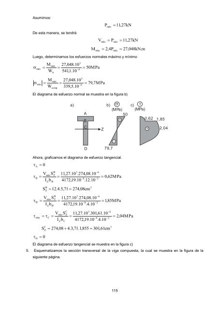
Asumimos: P máx 11,27kN De esta manera, se tendrá: M V máx máx P 2,4P máx máx 11,27kN 27,048kN.m Luego, <strong>de</strong>terminamos los esfuerzos normales máximo y mínimo máx M W máx tr 27,048.10 6 541,1.10 3 50MPa mín M W máx comp 27,048.10 339,5.10 3 6 79,7MPa El diagrama <strong>de</strong> esfuerzo normal se muestra en la figura b) a) b) c) (M P a) (M Pa) A 50 0,62 B + 1,85 C Z + 2,04 D 79,7 Ahora, graficamos el diagrama <strong>de</strong> esfuerzo tangencial. A 0 B V I máx Z b S B B Z 3 11,27.10 .274,08.10 8 4172,19.10 .12.10 6 2 0,62MPa B' S B Z V I Z 12.4.5,71 máx b S B' B Z 274,08cm 3 11,27.10 .274,08.10 8 4172,19.10 .4.10 3 6 2 1,85MPa máx C V I máx Z b S C C Z 3 11,27.10 .301,61.10 8 4172,19.10 .4.10 6 2 2,04MPa S C Z D 0 274,08 4.3,71.1,855 301,61cm El diagrama <strong>de</strong> esfuerzo tangencial se muestra en la figura c) 3 5. Esquematizamos la sección transversal <strong>de</strong> la viga compuesta, la cual se muestra en la figura <strong>de</strong> la siguiente página. 115
- Page 1 and 2:
MECANICA DE MATERIALES PRACTICAS Y
- Page 3 and 4:
PROLOGO La Mecánica de Materiales,
- Page 5 and 6:
MECANICA DE MATERIALES (CI80) PRACT
- Page 7 and 8:
6. ¿Qué esfuerzos se producirán
- Page 9 and 10:
3. Determinamos los esfuerzos:
- Page 11 and 12:
T 10.10 0,0040 .0,75 14,5.10 .1,30
- Page 13 and 14:
2. Se tiene un peso de 3T sostenido
- Page 15 and 16:
SOLUCIONARIO DE PRÁCTICA CALIFICAD
- Page 17 and 18:
o o F Y 0 239,062 F2sen30 (F2 3
- Page 19 and 20:
19 De donde: c c al al c c al al c
- Page 21 and 22:
A B D E 2 C 3. Determine el alargam
- Page 23 and 24:
SOLUCIONARIO DE PRÁCTICA CALIFICAD
- Page 25 and 26:
c 40.10 10.10 3 4 40MPa El diag
- Page 27 and 28:
Reemplazamos (b) en (a): En consecu
- Page 29 and 30:
2 b x L x SECCIÓN TRANSVERSAL b t
- Page 31 and 32:
SOLUCIONARIO DE PRÁCTICA CALIFICAD
- Page 33 and 34:
P B B P=40kN C 4m 2m D Luego, la ba
- Page 35 and 36:
C O B R E A B 1,1m RB A L U M I N
- Page 37 and 38:
MECANICA DE MATERIALES (CI80) PRACT
- Page 39 and 40:
L 1 2 A B a a 6. En el sistema estr
- Page 41 and 42:
=Tsen T Z T Z T Z T Z W Esquematiza
- Page 43 and 44:
Luego: E f f E Reemplazamos (f)
- Page 45 and 46:
MECANICA DE MATERIALES (CI80) EXAME
- Page 47 and 48:
SOLUCIONARIO DE EXAMEN PARCIAL CICL
- Page 49 and 50:
X 20 10 3 3 2 I3 XY Y YZ 10 0 10
- Page 51 and 52:
Reducción T0 Tf del par T 0 (100
- Page 53 and 54:
MECANICA DE MATERIALES (CI80) EXAME
- Page 55 and 56:
1. Como: SOLUCIONARIO DE EXAMEN PAR
- Page 57 and 58:
TBL T(3L / 4) GI GI p p 2T(L / 4)
- Page 59 and 60:
MECANICA DE MATERIALES (CI80) EXAME
- Page 61 and 62:
1. Como: Luego: Dividimos (b) entre
- Page 63 and 64: Restamos (f) menos (e): Además: De
- Page 65 and 66: 65 d a d b d x x L Además: 4 t d I
- Page 67 and 68: P a a a 4. Refiriéndose a la barra
- Page 69 and 70: 1. Por dato del problema: SOLUCIONA
- Page 71 and 72: Efectuando operaciones obtenemos: 3
- Page 73 and 74: MECANICA DE MATERIALES (CI80) EXAME
- Page 75 and 76: 1. Se sabe que: SOLUCIONARIO DE EXA
- Page 77 and 78: c) Determinamos el esfuerzo tangenc
- Page 79 and 80: MECANICA DE MATERIALES (CI80) PRACT
- Page 81 and 82: SOLUCIONARIO DE PRÁCTICA CALIFICAD
- Page 83 and 84: I z 0,16.0,3 12 3 0,05.0,26 2 12
- Page 85 and 86: CONCRETO: M c máx máx máx c y
- Page 87 and 88: 4. Elegir el perfil I más adecuado
- Page 89 and 90: y máx d I Z 4 d 4. 64 d 4 2
- Page 91 and 92: Aplicamos la condición de resisten
- Page 93 and 94: MECANICA DE MATERIALES (CI80) PRACT
- Page 95 and 96: SOLUCIONARIO DE PRÁCTICA CALIFICAD
- Page 97 and 98: M x 1,5m 0,5P 22,41 P 44,82kN
- Page 99 and 100: 6. Esquematizamos para la zona de c
- Page 101 and 102: Se pide: a) Elegir el perfil I más
- Page 103 and 104: 1. Por dato del problema: sup in
- Page 105 and 106: B V máx I Z S b B Z 3 42.10 .159
- Page 107 and 108: VS (V)(0,375b B 3 Z B' 1,519 0,
- Page 109 and 110: Posteriormente, aplicamos las condi
- Page 111 and 112: C 1,1m A q 1,6m I B 1,1m D SECCION
- Page 113: A 0,8q VIGA CD: Graficamos el diagr
- Page 117 and 118: De los resultados obtenidos, elegim
- Page 119 and 120: 4. METODO DE LA VIGA CONJUGADA. La
- Page 121 and 122: Orientamos el momento en A en senti
- Page 123 and 124: 4. a) BARRA ESCALONADA PL 2E 2 PL 2
- Page 125 and 126: MECANICA DE MATERIALES (CI80) PRACT
- Page 127 and 128: SOLUCIONARIO DE PRÁCTICA CALIFICAD
- Page 129 and 130: PRINCIPIO DE CONTINUIDAD: c) Si x
- Page 131 and 132: Ahora, lo transformamos en viga con
- Page 133 and 134: 4. METODO DE LA VIGA CONJUGADA. Par
- Page 135 and 136: CONDICIONES: a) Si x 0 0 b) Si
- Page 137 and 138: 3 L a x EIy P C1x C L 6 CO
- Page 139 and 140: Para determinar la ecuación de la
- Page 141 and 142: 4. METODO DE LA VIGA CONJUGADA. Par
- Page 143 and 144: De esta manera, la ecuación quedar
- Page 145 and 146: VA x EIy' 2 VA x EIy 6 CONDICIONE
- Page 147 and 148: 5. Liberamos el apoyo en C, lo reem
- Page 149 and 150: 4. METODO DE LA VIGA CONJUGADA. Par
- Page 151 and 152: Px EIy' 2 Px EIy 6 2 3 3P(x a)
- Page 153 and 154: ECUACION DE LA CURVA DE DEFLEXION:
- Page 155 and 156: Con los diagramas obtenidos, aplica
- Page 157 and 158: MECANICA DE MATERIALES (CI80) EXAME
- Page 159 and 160: SOLUCIONARIO DE EXAMEN FINAL CICLO
- Page 161 and 162: Luego: 1 2. EI PL 3EI L 1 EI 1
- Page 163 and 164: Luego: 227,276P 5509,158 0 EA P
- Page 165 and 166:
4. TEOREMA DE CASTIGLIANO. Una viga
- Page 167 and 168:
Determinamos la deflexión vertical
- Page 169 and 170:
DESPLAZAMIENTO HORIZONTAL EN “D
- Page 171 and 172:
TRAMO BC ( 0 x 3) M I M V V x 10
- Page 173 and 174:
4. TEOREMA DE CASTIGLIANO. Para la
- Page 175 and 176:
Ahora, aplicamos una carga vertical
- Page 177 and 178:
TRAMO AB ( 0 x 3a) M I M I Q P1
- Page 179 and 180:
c) 25,625 d) + 15,625 14,375 112,5
- Page 181 and 182:
4. TEOREMA DE CASTIGLIANO. Para la
- Page 183 and 184:
0,1111 El signo negativo, indica qu
- Page 185 and 186:
TRAMO AB ( 0 x L) M I M kM N
- Page 187 and 188:
EA 2EA EA MECANICA DE MATERIALES (C
- Page 189 and 190:
SOLUCIONARIO DE EXAMEN FINAL CICLO
- Page 191 and 192:
PENDIENTE EN “A”: A 1 EI 1
- Page 193 and 194:
TRAMO II-II ( 1 x 2) M II M H II
- Page 195:
INDICE PROLOGO…………………