- Page 1 and 2:
Design and Construction Handbook Ap
- Page 3 and 4:
1.31.6 Utilities 1.31.7 Product, Ma
- Page 5 and 6:
22.11.00 Facility Water Distributio
- Page 7 and 8:
Supplemental Drawings (To be issued
- Page 9 and 10:
1.0 General Requirements 1.1 Scope,
- Page 11 and 12:
inclusive of all information availa
- Page 13 and 14:
The 2008 Los Angeles Electrical Cod
- Page 15 and 16:
Design and Construction Handbook 15
- Page 17 and 18:
1.15 Tenant Projects Approvals - Te
- Page 19 and 20:
Issues Addressed Design Impacts to
- Page 21 and 22:
e responsible for assisting in the
- Page 23 and 24:
c. Egress Plan • Update Occupant
- Page 25 and 26:
• Locate and identify employee ch
- Page 27 and 28:
• Update sprinkler layout. • In
- Page 29 and 30:
g. Zone Plan (if required). • Ind
- Page 31 and 32:
• Identify all primary materials
- Page 33 and 34:
• Locate all receptacles • Loca
- Page 35 and 36:
3. Final Construction schedule, inc
- Page 37 and 38:
Design and Construction Handbook 37
- Page 39 and 40:
Mechanical Drawings: a. Sheet Index
- Page 41 and 42:
Communication Drawings: a. Sheet In
- Page 43 and 44:
• Make certain that the signature
- Page 45 and 46:
1. Piping shall be coordinated with
- Page 47 and 48:
other facilities. Constantly secure
- Page 49 and 50:
d. The face of the barricade expose
- Page 51 and 52:
e) No unapproved signage such as wa
- Page 53 and 54:
Design and Construction Handbook 53
- Page 55 and 56:
1.31.6 Utilities A. Pursuant to Sec
- Page 57 and 58:
Utility Shutdowns A. Utility shutdo
- Page 59 and 60:
Deviations: The Submittals shall cl
- Page 61 and 62: miscellaneous items, as included he
- Page 63 and 64: 5) The Contractor shall comply with
- Page 65 and 66: 1. Sediments or other surface water
- Page 67 and 68: Temporary Light, Power, Water, and
- Page 69 and 70: equirements listed and any other re
- Page 71 and 72: unauthorized persons to Airport-res
- Page 73 and 74: C. The Contractor shall notify the
- Page 75 and 76: E. All materials, parts, and equipm
- Page 77 and 78: N. See appendix B for typical items
- Page 79 and 80: or other characteristics, including
- Page 81 and 82: Design and Construction Handbook 81
- Page 83: GUIDE SPECIFICATIONS INTRODUCTION I
- Page 86 and 87: Guide Specification bolts, and item
- Page 88 and 89: Guide Specification 2. Wall Bracket
- Page 90 and 91: Guide Specification 3.4 METAL BASE
- Page 92 and 93: Guide Specification 1.5 CLOSEOUT SU
- Page 94 and 95: Guide Specification 2.3 ILLUMINATIO
- Page 96 and 97: Guide Specification B. Glass Column
- Page 98 and 99: Guide Specification SECTION 06 40 2
- Page 100 and 101: Guide Specification humidity at lev
- Page 102 and 103: Guide Specification B. Solid-Surfac
- Page 104 and 105: Guide Specification SECTION 08 11 1
- Page 106 and 107: Guide Specification 1.4 DELIVERY, S
- Page 108 and 109: Guide Specification 7. Exit Device
- Page 110 and 111: Guide Specification a. Three anchor
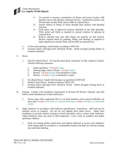
- Page 114 and 115: Guide Specification 3.2 ADJUSTING A
- Page 116 and 117: Guide Specification 1.3 INFORMATION
- Page 118 and 119: Guide Specification a. Welded Steel
- Page 120 and 121: Guide Specification b. Stud-Wall Ty
- Page 122 and 123: Guide Specification B. Stainless-St
- Page 124 and 125: Guide Specification B. Examine roug
- Page 126 and 127: Guide Specification D. Glazing: Ins
- Page 128 and 129: Guide Specification DOOR HARDWARE 0
- Page 130 and 131: Guide Specification 1.5 COORDINATIO
- Page 132 and 133: Guide Specification 2.2 HINGING MET
- Page 134 and 135: Guide Specification 1. 1100 Series
- Page 136 and 137: Guide Specification B. Size: Furnis
- Page 138 and 139: Guide Specification 1. All modifica
- Page 140 and 141: Guide Specification SECTION 09 22 1
- Page 142 and 143: Guide Specification a. Diameter: 1/
- Page 144 and 145: Guide Specification NOTE: On the dr
- Page 146 and 147: Guide Specification 3.5 INSTALLING
- Page 148 and 149: GYPSUM BOARD 09 29 00 - 1 Guide Spe
- Page 150 and 151: Guide Specification NOTE: d. On the
- Page 152 and 153: GYPSUM BOARD 09 29 00 - 5 Guide Spe
- Page 154 and 155: GYPSUM BOARD 09 29 00 - 7 Guide Spe
- Page 156 and 157: GYPSUM BOARD 09 29 00 - 9 Guide Spe
- Page 158 and 159: Guide Specification 1. Locate sampl
- Page 160 and 161: Guide Specification 2. Latex Additi
- Page 162 and 163:
Guide Specification F. Movement (Ex
- Page 164 and 165:
Guide Specification c. Immediately
- Page 166 and 167:
Guide Specification SECTION 09 51 1
- Page 168 and 169:
Guide Specification Testing of Vola
- Page 170 and 171:
Guide Specification SECTION 09 66 1
- Page 172 and 173:
Guide Specification 1. Build mockup
- Page 174 and 175:
Guide Specification D. Control-Join
- Page 176 and 177:
Guide Specification B. Installation
- Page 178 and 179:
Guide Specification SECTION 09 66 2
- Page 180 and 181:
Guide Specification 1.6 PROTECTION
- Page 182 and 183:
Guide Specification 1. Sizes shall
- Page 184 and 185:
Guide Specification NOTE: the mix d
- Page 186 and 187:
Guide Specification 4. Curing: Allo
- Page 188 and 189:
Guide Specification 1. Probe Manufa
- Page 190 and 191:
Guide Specification b. Stop Strips:
- Page 192 and 193:
Guide Specification thoroughly. App
- Page 194 and 195:
Guide Specification 1. Each carpet
- Page 196 and 197:
Guide Specification F. Density: Gre
- Page 198 and 199:
Guide Specification C. Butt carpet
- Page 200 and 201:
Guide Specification 4. Mitered Carp
- Page 202 and 203:
Guide Specification 4. Mannington 5
- Page 204 and 205:
Guide Specification characteristics
- Page 206 and 207:
Guide Specification END OF SECTION
- Page 208 and 209:
Guide Specification 4. ICI Paints 5
- Page 210 and 211:
Guide Specification 3.3 APPLICATION
- Page 212 and 213:
SIGNAGE 10 14 23 - 1 Guide Specific
- Page 214 and 215:
SIGNAGE 10 14 23 - 3 Guide Specific
- Page 216 and 217:
SIGNAGE 10 14 23 - 5 Guide Specific
- Page 218 and 219:
SIGNAGE 10 14 23 - 7 Guide Specific
- Page 220 and 221:
SIGNAGE 10 14 23 - 9 Guide Specific
- Page 222 and 223:
SIGNAGE 10 14 23 - 11 Guide Specifi
- Page 224 and 225:
SIGNAGE 10 14 23 - 13 Guide Specifi
- Page 226 and 227:
SIGNAGE 10 14 23 - 15 Guide Specifi
- Page 228 and 229:
SIGNAGE 10 14 23 - 17 Guide Specifi
- Page 230 and 231:
Guide Specification SECTION 10 21 1
- Page 232 and 233:
Guide Specification END OF SECTION
- Page 234 and 235:
2.2 CORNER GUARDS A. Surface-Mounte
- Page 236 and 237:
2. Provide full height units. Do no
- Page 238 and 239:
Guide Specification 1.4 COORDINATIO
- Page 240 and 241:
Guide Specification 2. Mounting: Fl
- Page 242 and 243:
Guide Specification 2.6 CUSTODIAL A
- Page 244 and 245:
Guide Specification 1. Review metho
- Page 246 and 247:
Guide Specification B. Cabinet Door
- Page 248 and 249:
Guide Specification SECTION 10 44 1
- Page 250 and 251:
Guide Specification 1. Shelf: Same
- Page 252 and 253:
Guide Specification 3.3 INSTALLATIO
- Page 254 and 255:
Guide Specification 1.7 WARRANTY A.
- Page 256 and 257:
Guide Specification SECTION 12 24 1
- Page 258 and 259:
Guide Specification H. Shade Cloth
- Page 260 and 261:
Guide Specification 4. The braking
- Page 262 and 263:
Guide Specification d. Multiple "su
- Page 264 and 265:
Guide Specification SECTION 14 20 0
- Page 266 and 267:
Guide Specification c. Single-phase
- Page 268 and 269:
Guide Specification a. Clear, plumb
- Page 270 and 271:
Guide Specification j. Single phase
- Page 272 and 273:
Guide Specification 3. All electric
- Page 274 and 275:
Guide Specification when copies of
- Page 276 and 277:
Guide Specification 15) Safeties: C
- Page 278 and 279:
Guide Specification safety devices
- Page 280 and 281:
Guide Specification LAWA. This serv
- Page 282 and 283:
Guide Specification 1) Replace: Rep
- Page 284 and 285:
Guide Specification 2.1 MATERIALS A
- Page 286 and 287:
Guide Specification A. General: On
- Page 288 and 289:
Guide Specification SECTION 14 21 0
- Page 290 and 291:
Guide Specification 2. Samples shal
- Page 292 and 293:
Guide Specification 1.5 DELIVERY, S
- Page 294 and 295:
Guide Specification B. Optional Sec
- Page 296 and 297:
Guide Specification L. Baked Enamel
- Page 298 and 299:
Guide Specification Car and Hoistwa
- Page 300 and 301:
Guide Specification C. Door Control
- Page 302 and 303:
Guide Specification O. Terminal Lim
- Page 304 and 305:
Guide Specification 2. Include as a
- Page 306 and 307:
Guide Specification d. Elevator dep
- Page 308 and 309:
Guide Specification 3. Protect car
- Page 310 and 311:
Guide Specification a minimum dimen
- Page 312 and 313:
Guide Specification F. Hall Lantern
- Page 314 and 315:
Guide Specification seconds. Upon e
- Page 316 and 317:
Guide Specification 9. All cabinets
- Page 318 and 319:
Guide Specification C. Re-Inspectio
- Page 320 and 321:
Guide Specification D. Step/Skirt P
- Page 322 and 323:
Guide Specification K. Operation an
- Page 324 and 325:
Guide Specification A. Installer Qu
- Page 326 and 327:
Guide Specification 2.2 MATERIALS A
- Page 328 and 329:
Guide Specification 3. Brake Operat
- Page 330 and 331:
Guide Specification a. The motor co
- Page 332 and 333:
Guide Specification 5. Step Tracks:
- Page 334 and 335:
Guide Specification ends. Plates sh
- Page 336 and 337:
Guide Specification building change
- Page 338 and 339:
Guide Specification 35) Pit high wa
- Page 340 and 341:
Guide Specification 3.4 DEMONSTRATI
- Page 342 and 343:
Guide Specification 1.4 QUALITY ASS
- Page 344 and 345:
Guide Specification a. Tools may be
- Page 346 and 347:
Guide Specification 1.6 JOB CONDITI
- Page 348 and 349:
Guide Specification C. Oil Drip Pan
- Page 350 and 351:
Guide Specification G. Landing Floo
- Page 352 and 353:
Guide Specification 1. Provide each
- Page 354 and 355:
Guide Specification 1. Per Referenc
- Page 356 and 357:
Guide Specification 1. Emergency St
- Page 358 and 359:
Guide Specification F. Width: 56" (
- Page 360 and 361:
Guide Specification PART 2 - PRODUC
- Page 362 and 363:
Guide Specification PART 3 - EXECUT
- Page 364 and 365:
Guide Specification SECTION 21 05 1
- Page 366 and 367:
Guide Specification 4. Joint: As sp
- Page 368 and 369:
Guide Specification 3.2 MANUFACTURE
- Page 370 and 371:
Guide Specification PART 2 - PRODUC
- Page 372 and 373:
Guide Specification SECTION 21 13 1
- Page 374 and 375:
Guide Specification 2.2 PIPING SPEC
- Page 376 and 377:
Guide Specification SECTION 21 13 1
- Page 378 and 379:
Guide Specification 1. Type: Standa
- Page 380 and 381:
Guide Specification SECTION 21 22 0
- Page 382 and 383:
2.4 VALVES Guide Specification a. M
- Page 384 and 385:
Guide Specification B. Manual Relea
- Page 386 and 387:
Guide Specification 3.3 CLEAN-AGENT
- Page 388 and 389:
Guide Specification 1.3 SUBMITTALS
- Page 390 and 391:
Guide Specification C. 2-1/2 inches
- Page 392 and 393:
Guide Specification 2.5 BUTTERFLY V
- Page 394 and 395:
Guide Specification 3.3 GENERAL REQ
- Page 396 and 397:
Guide Specification SECTION 22 05 2
- Page 398 and 399:
Guide Specification 1. Hangers for
- Page 400 and 401:
Guide Specification 2.9 FIRESTOPPIN
- Page 402 and 403:
Guide Specification 2.13 PIPE POSIT
- Page 404 and 405:
Guide Specification 20. Pipe Roll a
- Page 406 and 407:
Guide Specification auxiliary stops
- Page 408 and 409:
Guide Specification d. NPS 8 to NPS
- Page 410 and 411:
Guide Specification N. Spring suppo
- Page 412 and 413:
Guide Specification SECTION 22 05 4
- Page 414 and 415:
Guide Specification 1. Mass: Minimu
- Page 416 and 417:
Guide Specification a. 0.750 inch m
- Page 418 and 419:
Guide Specification 2.5 SEISMIC RES
- Page 420 and 421:
Guide Specification D. Install spri
- Page 422 and 423:
Guide Specification H. Drilled-in A
- Page 424 and 425:
Guide Specification SECTION 22 05 5
- Page 426 and 427:
2.3 STENCILS Guide Specification c.
- Page 428 and 429:
Guide Specification B. Valve Lockou
- Page 430 and 431:
Guide Specification 2. Near each br
- Page 432 and 433:
Guide Specification SECTION 22 07 0
- Page 434 and 435:
Guide Specification C. Mockups: Bef
- Page 436 and 437:
Guide Specification H. TYPE P-8: AS
- Page 438 and 439:
Guide Specification E. Closed Cell
- Page 440 and 441:
Guide Specification D. Mineral Fibe
- Page 442 and 443:
Guide Specification 3. Service Temp
- Page 444 and 445:
Guide Specification C. Woven Polyes
- Page 446 and 447:
Guide Specification C. Stainless-St
- Page 448 and 449:
Guide Specification N. Heat Traced
- Page 450 and 451:
Guide Specification PIPING SYSTEM D
- Page 452 and 453:
Guide Specification SECTION 22 11 0
- Page 454 and 455:
Guide Specification 1. Mechanical-J
- Page 456 and 457:
Guide Specification B. Remote Regis
- Page 458 and 459:
Guide Specification 3. Stem: Copper
- Page 460 and 461:
Guide Specification a. Watts. b. Zu
- Page 462 and 463:
Guide Specification C. Refrigerator
- Page 464 and 465:
Guide Specification 3. Refrigerator
- Page 466 and 467:
Guide Specification SECTION 22 13 0
- Page 468 and 469:
Guide Specification PART 2 - PRODUC
- Page 470 and 471:
Guide Specification 2.3 SANITARY SE
- Page 472 and 473:
Guide Specification 1. Copper Pipin
- Page 474 and 475:
Guide Specification 13. Type, for E
- Page 476 and 477:
Guide Specification B. Cast Iron: A
- Page 478 and 479:
Guide Specification 1. Structural D
- Page 480 and 481:
Guide Specification D. Keep open en
- Page 482 and 483:
Guide Specification sanitary sewer
- Page 484 and 485:
Guide Specification 7. NPS 6: 12 fe
- Page 486 and 487:
Guide Specification Q. Install expa
- Page 488 and 489:
Guide Specification END OF SECTION
- Page 490 and 491:
Guide Specification B. Manufacturer
- Page 492 and 493:
Guide Specification B. Ductile-Iron
- Page 494 and 495:
Guide Specification 2.6 STORM WATER
- Page 496 and 497:
Guide Specification C. Area Drain (
- Page 498 and 499:
Guide Specification C. Cover shall
- Page 500 and 501:
Guide Specification 1. Power failur
- Page 502 and 503:
Guide Specification 1. Galvanized s
- Page 504 and 505:
Guide Specification 3. Multiple, St
- Page 506 and 507:
Guide Specification 1. Lead Sheets:
- Page 508 and 509:
Guide Specification SECTION 22 31 0
- Page 510 and 511:
Guide Specification b. Everpure, In
- Page 512 and 513:
Guide Specification PART 2 - PRODUC
- Page 514 and 515:
Guide Specification SECTION 22 34 0
- Page 516 and 517:
Guide Specification 1. Rheem. 2. A.
- Page 518 and 519:
Guide Specification a. Thermometer
- Page 520 and 521:
Guide Specification E. Shop Drawing
- Page 522 and 523:
Guide Specification a. J.R. Smith.
- Page 524 and 525:
Guide Specification 1. Sloan. 2. Ch
- Page 526 and 527:
Guide Specification pitched to drai
- Page 528 and 529:
2.9 MOP SINKS Guide Specification A
- Page 530 and 531:
Guide Specification I. Install wate
- Page 532 and 533:
Guide Specification SECTION 22 70 0
- Page 534 and 535:
Guide Specification PART 2 - PRODUC
- Page 536 and 537:
Guide Specification B. Product Desc
- Page 538 and 539:
Guide Specification B. Manufacturer
- Page 540 and 541:
Guide Specification 6. Ends: Thread
- Page 542 and 543:
Guide Specification D. Gas safety s
- Page 544 and 545:
Guide Specification E. One-Piece, S
- Page 546 and 547:
Guide Specification C. Install gas
- Page 548 and 549:
Guide Specification e. Piping in Eq
- Page 550 and 551:
Guide Specification B. Install hang
- Page 552 and 553:
Guide Specification C. Source Quali
- Page 554 and 555:
Guide Specification h. Insert 2 cop
- Page 556 and 557:
Guide Specification D. Access to Eq
- Page 558 and 559:
Guide Specification and frames shal
- Page 560 and 561:
Guide Specification 4. Purge all ai
- Page 562 and 563:
Guide Specification B. Product Data
- Page 564 and 565:
Guide Specification 2.3 ACCESSORIES
- Page 566 and 567:
Guide Specification PART 2 - PRODUC
- Page 568 and 569:
Guide Specification 1. Manufacturer
- Page 570 and 571:
Guide Specification 3.3 CHILLED-WAT
- Page 572 and 573:
Guide Specification SECTION 23 05 2
- Page 574 and 575:
Guide Specification D. Design Data:
- Page 576 and 577:
Guide Specification C. Low-Type, Si
- Page 578 and 579:
Guide Specification 2.11 FIRESTOPPI
- Page 580 and 581:
Guide Specification C. Construct su
- Page 582 and 583:
Guide Specification SECTION 23 05 4
- Page 584 and 585:
Guide Specification C. Restrained S
- Page 586 and 587:
Guide Specification 2.3 DUCTWORK LA
- Page 588 and 589:
Guide Specification 3. Wedge Anchor
- Page 590 and 591:
Guide Specification PART 2 - PRODUC
- Page 592 and 593:
Guide Specification 2. Brady. 3. Ko
- Page 594 and 595:
Guide Specification 3.2 INSTALLATIO
- Page 596 and 597:
Guide Specification drawings with a
- Page 598 and 599:
Guide Specification B. Permanently
- Page 600 and 601:
Guide Specification D. Measure, adj
- Page 602 and 603:
Guide Specification c. Size/model d
- Page 604 and 605:
Guide Specification k. Discharge pr
- Page 606 and 607:
Guide Specification h. Minimum desi
- Page 608 and 609:
Guide Specification 18. ASTM C1136
- Page 610 and 611:
Guide Specification H. TYPE P-8: AS
- Page 612 and 613:
Guide Specification 2. Density: 1.5
- Page 614 and 615:
Guide Specification b. Pittsburgh C
- Page 616 and 617:
Guide Specification 1. Insulate ent
- Page 618 and 619:
Guide Specification P. Prepare pipe
- Page 620 and 621:
Guide Specification G. Equipment in
- Page 622 and 623:
Guide Specification Transfer Air Du
- Page 624 and 625:
Guide Specification SECTION 23 08 0
- Page 626 and 627:
Guide Specification 1.7 COMMISSIONI
- Page 628 and 629:
Guide Specification 2. Piping syste
- Page 630 and 631:
Guide Specification 1. Test heating
- Page 632 and 633:
Guide Specification 4. System confi
- Page 634 and 635:
Guide Specification 2.2 OPERATOR WO
- Page 636 and 637:
Guide Specification 6. Record, eval
- Page 638 and 639:
Guide Specification 5. Add, delete,
- Page 640 and 641:
Guide Specification 6. Data reports
- Page 642 and 643:
Guide Specification a. Start. b. Op
- Page 644 and 645:
Guide Specification 2. Base on occu
- Page 646 and 647:
Guide Specification 1. Calculate ou
- Page 648 and 649:
Guide Specification PART 3 - EXECUT
- Page 650 and 651:
Guide Specification 1.3 SYSTEM DESC
- Page 652 and 653:
Guide Specification 1. Fittings: AS
- Page 654 and 655:
Guide Specification D. Sleeve pipe
- Page 656 and 657:
Guide Specification PIPE SIZE Inche
- Page 658 and 659:
Guide Specification B. Type: Horizo
- Page 660 and 661:
Guide Specification SECTION 23 23 0
- Page 662 and 663:
Guide Specification B. Line Test Pr
- Page 664 and 665:
Guide Specification 2.4 REFRIGERANT
- Page 666 and 667:
Guide Specification 3. Sporlan Valv
- Page 668 and 669:
Guide Specification B. Internal Dia
- Page 670 and 671:
Guide Specification 2. When receive
- Page 672 and 673:
Guide Specification SECTION 23 25 0
- Page 674 and 675:
Guide Specification 1. Water meters
- Page 676 and 677:
Guide Specification 5. High or low
- Page 678 and 679:
Guide Specification C. Provide glyc
- Page 680 and 681:
Guide Specification source and allo
- Page 682 and 683:
Guide Specification Metal and Flexi
- Page 684 and 685:
Guide Specification 3. AWS D9.1M/D9
- Page 686 and 687:
Guide Specification 1. Ducts up to
- Page 688 and 689:
Guide Specification 7. Maximum Stat
- Page 690 and 691:
Guide Specification D. Unless other
- Page 692 and 693:
Guide Specification 8. Unconditione
- Page 694 and 695:
3.9 PAINTING Guide Specification A.
- Page 696 and 697:
3.12 START UP Guide Specification 2
- Page 698 and 699:
Guide Specification a. Pressure Cla
- Page 700 and 701:
Guide Specification a. Rectangular
- Page 702 and 703:
Guide Specification 2. UL 555C - St
- Page 704 and 705:
Guide Specification 9. 90-degree st
- Page 706 and 707:
Guide Specification B. Fabrication:
- Page 708 and 709:
Guide Specification 3. Operator: Mi
- Page 710 and 711:
Guide Specification F. Bearings: 1.
- Page 712 and 713:
Guide Specification h. Upstream and
- Page 714 and 715:
Guide Specification 3.2 NSTALLATION
- Page 716 and 717:
Guide Specification 1.3 SUBMITTALS
- Page 718 and 719:
Guide Specification C. Sheaves: Cas
- Page 720 and 721:
Guide Specification SECTION 23 36 0
- Page 722 and 723:
Guide Specification H. Hot Water He
- Page 724 and 725:
Guide Specification SECTION 23 37 0
- Page 726 and 727:
Guide Specification 2.5 CEILING SUP
- Page 728 and 729:
Guide Specification D. Fabrication:
- Page 730 and 731:
Guide Specification SECTION 23 40 0
- Page 732 and 733:
Guide Specification C. Media: UL 90
- Page 734 and 735:
Guide Specification 9. An integral
- Page 736 and 737:
Guide Specification 1.4 WARRANTY in
- Page 738 and 739:
Guide Specification SECTION 23 64 1
- Page 740 and 741:
Guide Specification PART 2 - PRODUC
- Page 742 and 743:
Guide Specification B. Coil Guard:
- Page 744 and 745:
Guide Specification C. Install the
- Page 746 and 747:
Guide Specification E. If chiller a
- Page 748 and 749:
Guide Specification SECTION 23 64 1
- Page 750 and 751:
Guide Specification 1.4 WARRANTY c.
- Page 752 and 753:
Guide Specification motor and motor
- Page 754 and 755:
Guide Specification 1. Type: R-134a
- Page 756 and 757:
Guide Specification C. Designed to
- Page 758 and 759:
Guide Specification C. Enclosure: U
- Page 760 and 761:
Guide Specification 12. Total power
- Page 762 and 763:
Guide Specification E. Manually Res
- Page 764 and 765:
Guide Specification sagging. D. Too
- Page 766 and 767:
Guide Specification mechanical coup
- Page 768 and 769:
Guide Specification 3.7 COMMISSIONI
- Page 770 and 771:
Guide Specification SECTION 23 65 0
- Page 772 and 773:
Guide Specification 7. Fan airflow,
- Page 774 and 775:
Guide Specification 1. Material: St
- Page 776 and 777:
Guide Specification GUARANTEED MINI
- Page 778 and 779:
Guide Specification 4. Handrail: St
- Page 780 and 781:
Guide Specification h. Verify prope
- Page 782 and 783:
Guide Specification 1. NEMA MG 1 -
- Page 784 and 785:
Guide Specification 1. Zinc chromat
- Page 786 and 787:
2.5 COILS Guide Specification A. Ca
- Page 788 and 789:
Guide Specification d. Axles: Minim
- Page 790 and 791:
Guide Specification Method for Test
- Page 792 and 793:
Guide Specification END OF SECTION
- Page 794 and 795:
Guide Specification 4. Rough-in con
- Page 796 and 797:
Guide Specification K. Air Filters:
- Page 798 and 799:
Guide Specification 3.3 MANUFACTURE
- Page 800 and 801:
Guide Specification f. National Fir
- Page 802 and 803:
Guide Specification 32. Resistive L
- Page 804 and 805:
Guide Specification 1.6 MAINTENANCE
- Page 806 and 807:
Guide Specification deems a critica
- Page 808 and 809:
Guide Specification 1. Hubbell. 2.
- Page 810 and 811:
Guide Specification SECTION 26 05 1
- Page 812 and 813:
Guide Specification B. Location: In
- Page 814 and 815:
Guide Specification B. Inspect cabl
- Page 816 and 817:
Guide Specification 3.1 CONDUCTOR A
- Page 818 and 819:
Guide Specification SECTION 26 05 1
- Page 820 and 821:
Guide Specification 2.3 TERMINATION
- Page 822 and 823:
Guide Specification SECTION 26 05 2
- Page 824 and 825:
Guide Specification 2.1 ROD ELECTRO
- Page 826 and 827:
Guide Specification J. Install from
- Page 828 and 829:
Guide Specification 1.3 DEFINITIONS
- Page 830 and 831:
Guide Specification damage, by stor
- Page 832 and 833:
Guide Specification 5. Mechanical F
- Page 834 and 835:
Guide Specification spring lock was
- Page 836 and 837:
Guide Specification A. Clean adjace
- Page 838 and 839:
Guide Specification F. In Slab Abov
- Page 840 and 841:
Guide Specification 2. Allied Tube
- Page 842 and 843:
Guide Specification 1. Material: Ga
- Page 844 and 845:
Guide Specification U. Install suit
- Page 846 and 847:
Guide Specification SECTION 26 05 3
- Page 848 and 849:
Guide Specification B. Product Desc
- Page 850 and 851:
Guide Specification SECTION 26 05 4
- Page 852 and 853:
Guide Specification 1.6 PROJECT CON
- Page 854 and 855:
Guide Specification C. Design and f
- Page 856 and 857:
Guide Specification clean surfaces
- Page 858 and 859:
Guide Specification with structural
- Page 860 and 861:
Guide Specification 3.4 MANHOLE AND
- Page 862 and 863:
Guide Specification SECTION 26 05 4
- Page 864 and 865:
Guide Specification PART 2 - PRODUC
- Page 866 and 867:
Guide Specification D. Holes for Ex
- Page 868 and 869:
Guide Specification SECTION 26 05 5
- Page 870 and 871:
Guide Specification voltage between
- Page 872 and 873:
Guide Specification locations. 6. I
- Page 874 and 875:
Guide Specification 1.2 REFERENCES
- Page 876 and 877:
Guide Specification 1.4 SUBMITTALS
- Page 878 and 879:
Guide Specification 1.5 QUALITY ASS
- Page 880 and 881:
Guide Specification B. Arc fault ha
- Page 882 and 883:
Guide Specification description of
- Page 884 and 885:
Guide Specification equipment for t
- Page 886 and 887:
Guide Specification 3.7 MANUFACTURE
- Page 888 and 889:
Guide Specification and type of swi
- Page 890 and 891:
Guide Specification 1. Cover Mounte
- Page 892 and 893:
Guide Specification 2. Separate tri
- Page 894 and 895:
Guide Specification SECTION 26 09 4
- Page 896 and 897:
Guide Specification D. Provide 2 ex
- Page 898 and 899:
Guide Specification 5. The DTC shal
- Page 900 and 901:
Guide Specification 3.2 DOCUMENTATI
- Page 902 and 903:
Guide Specification SECTION 26 13 1
- Page 904 and 905:
Guide Specification the installatio
- Page 906 and 907:
Guide Specification Maximum Voltage
- Page 908 and 909:
Guide Specification F. Each breaker
- Page 910 and 911:
Guide Specification u. Demand and P
- Page 912 and 913:
Guide Specification B. Voltage and
- Page 914 and 915:
Guide Specification a. Safety: UL 6
- Page 916 and 917:
Guide Specification b. Waveforms sh
- Page 918 and 919:
Guide Specification a. Eight (8) di
- Page 920 and 921:
Guide Specification A. The switchge
- Page 922 and 923:
Guide Specification ANSI standards.
- Page 924 and 925:
Guide Specification SECTION 26 22 0
- Page 926 and 927:
Guide Specification I. Basic Impuls
- Page 928 and 929:
Guide Specification B. Use flexible
- Page 930 and 931:
Guide Specification 10. Cable termi
- Page 932 and 933:
Guide Specification PART 2 - PRODUC
- Page 934 and 935:
2.4 BUS Guide Specification H. An i
- Page 936 and 937:
Guide Specification control circuit
- Page 938 and 939:
Guide Specification for remote sett
- Page 940 and 941:
Guide Specification 2.10 ENCLOSURES
- Page 942 and 943:
Guide Specification B. The training
- Page 944 and 945:
Guide Specification B. Product Data
- Page 946 and 947:
Guide Specification 2.2 MOLDED CASE
- Page 948 and 949:
Guide Specification C. Allow witnes
- Page 950 and 951:
Guide Specification 1.3 SUBMITTALS
- Page 952 and 953:
Guide Specification PART 3 - EXECUT
- Page 954 and 955:
Guide Specification C. Submit dimen
- Page 956 and 957:
Guide Specification B. Product Desc
- Page 958 and 959:
Guide Specification 3.3 INSTALLATIO
- Page 960 and 961:
Guide Specification 1.4 CLOSEOUT SU
- Page 962 and 963:
Guide Specification 3.2 FIELD QUALI
- Page 964 and 965:
Guide Specification 2.1 HINGED COVE
- Page 966 and 967:
Guide Specification SECTION 26 27 2
- Page 968 and 969:
Guide Specification C. Configuratio
- Page 970 and 971:
Guide Specification 3.7 CLEANING A.
- Page 972 and 973:
Guide Specification A. Manufacturer
- Page 974 and 975:
Guide Specification A. Manufacturer
- Page 976 and 977:
Guide Specification SECTION 26 28 2
- Page 978 and 979:
Guide Specification PART 3 - EXECUT
- Page 980 and 981:
Guide Specification A. Project Reco
- Page 982 and 983:
Guide Specification protected by ar
- Page 984 and 985:
Guide Specification E. Sequence of
- Page 986 and 987:
Guide Specification switch is in no
- Page 988 and 989:
Guide Specification 2.3 SOURCE QUAL
- Page 990 and 991:
Guide Specification SECTION 26 29 1
- Page 992 and 993:
Guide Specification 4. Pushbuttons:
- Page 994 and 995:
Guide Specification 1.4 SUBMITTALS
- Page 996 and 997:
Guide Specification B. Product Desc
- Page 998 and 999:
Guide Specification complete contro
- Page 1000 and 1001:
Guide Specification in accordance w
- Page 1002 and 1003:
Guide Specification 2.10 RADIATOR M
- Page 1004 and 1005:
Guide Specification connecting to t
- Page 1006 and 1007:
Guide Specification SECTION 26 33 0
- Page 1008 and 1009:
Guide Specification 3.1 INSTALLATIO
- Page 1010 and 1011:
Guide Specification B. Design Requi
- Page 1012 and 1013:
Guide Specification 1.5 SUBMITTALS
- Page 1014 and 1015:
Guide Specification 1. Wiring pract
- Page 1016 and 1017:
Guide Specification C. Inverter 7.
- Page 1018 and 1019:
Guide Specification (3) DC Under vo
- Page 1020 and 1021:
Guide Specification 5. Controls (2)
- Page 1022 and 1023:
Guide Specification 2. Isolation a.
- Page 1024 and 1025:
Guide Specification a. Eight sets o
- Page 1026 and 1027:
Guide Specification PART 3 - EXECUT
- Page 1028 and 1029:
Guide Specification SECTION 26 43 1
- Page 1030 and 1031:
Guide Specification and the followi
- Page 1032 and 1033:
Guide Specification 3. Neutral to G
- Page 1034 and 1035:
Guide Specification SECTION 26 51 0
- Page 1036 and 1037:
Guide Specification 1.11 WARRANTIES
- Page 1038 and 1039:
Guide Specification 1. Philips. 2.
- Page 1040 and 1041:
Guide Specification SECTION 27 50 0
- Page 1042 and 1043:
Guide Specification G. Submit all f
- Page 1044 and 1045:
Guide Specification 14. ANSI/TIA/EI
- Page 1046 and 1047:
Guide Specification 7. The listing
- Page 1048 and 1049:
Guide Specification H. The Contract
- Page 1050 and 1051:
Guide Specification B. Provide 4-po
- Page 1052 and 1053:
Guide Specification D. Acceptable M
- Page 1054 and 1055:
Guide Specification Baggage Handlin
- Page 1056 and 1057:
Guide Specification 3.2 PHASES OF I
- Page 1058 and 1059:
Guide Specification 3.7 SYSTEM STAR
- Page 1060 and 1061:
H. I. J. K. L. M. Guide Specificati
- Page 1062 and 1063:
Guide Specification 3.13 COMPUTERIZ
- Page 1064 and 1065:
Guide Specification 1.3 MATERIALS O
- Page 1066 and 1067:
Guide Specification E. Storage or s
- Page 1068 and 1069:
Guide Specification F. Existing Ite
- Page 1070 and 1071:
Guide Specification C. Refrigerant:
- Page 1072 and 1073:
Guide Specification SECTION 27 13 3
- Page 1074 and 1075:
Guide Specification F. Post changes
- Page 1076 and 1077:
Guide Specification 1.7 EQUIPMENT C
- Page 1078 and 1079:
Guide Specification Contractor is r
- Page 1080 and 1081:
Guide Specification PART 3 - EXECUT
- Page 1082 and 1083:
Guide Specification O. Spare condui
- Page 1084 and 1085:
Guide Specification 3.6 COMPUTERIZE
- Page 1086 and 1087:
Guide Specification O. NEMA Nationa
- Page 1088 and 1089:
Guide Specification 5. ANSI/TIA/EIA
- Page 1090 and 1091:
Guide Specification D. Major items
- Page 1092 and 1093:
Guide Specification 2. The system s
- Page 1094 and 1095:
Guide Specification 7. Web-Based/Cl
- Page 1096 and 1097:
Guide Specification 2.4 FIRESTOPPIN
- Page 1098 and 1099:
Guide Specification B. Upon concurr
- Page 1100 and 1101:
Guide Specification 7. Termination
- Page 1102 and 1103:
Guide Specification 1) After conclu
- Page 1104 and 1105:
Guide Specification C. All indoor c
- Page 1106 and 1107:
Guide Specification SECTION 27 51 1
- Page 1108 and 1109:
Guide Specification PAGING SYSTEMS
- Page 1110 and 1111:
Guide Specification C. System insta
- Page 1112 and 1113:
Guide Specification H. All audio sw
- Page 1114 and 1115:
Guide Specification 1. The PDRP sys
- Page 1116 and 1117:
Guide Specification S. Monitor/test
- Page 1118 and 1119:
Guide Specification PAGING SYSTEMS
- Page 1120 and 1121:
Guide Specification 1.6 QUALITY ASS
- Page 1122 and 1123:
Guide Specification warranty period
- Page 1124 and 1125:
Guide Specification 5. Intelligibil
- Page 1126 and 1127:
Guide Specification Custom software
- Page 1128 and 1129:
Guide Specification Fire Stop Syste
- Page 1130 and 1131:
Guide Specification 1. On-Site Perf
- Page 1132 and 1133:
Guide Specification D. Endurance Te
- Page 1134 and 1135:
Guide Specification PAGING SYSTEMS
- Page 1136 and 1137:
Guide Specification 5. Absence of g
- Page 1138 and 1139:
Guide Specification 3. Freedom From
- Page 1140 and 1141:
Guide Specification inspection, LAW
- Page 1142 and 1143:
Guide Specification security contra
- Page 1144 and 1145:
Guide Specification 1. Provide shop
- Page 1146 and 1147:
Guide Specification 10. Record draw
- Page 1148 and 1149:
Guide Specification 6. 49 CFR 1520
- Page 1150 and 1151:
Guide Specification 5. Where applic
- Page 1152 and 1153:
Guide Specification Contractor is r
- Page 1154 and 1155:
Guide Specification 2. GE DOR model
- Page 1156 and 1157:
Guide Specification a. Cooper Notif
- Page 1158 and 1159:
Guide Specification 2.6 FIRESTOPPIN
- Page 1160 and 1161:
Guide Specification a. Floors - thr
- Page 1162 and 1163:
Guide Specification 5. All equipmen
- Page 1164 and 1165:
Guide Specification 3.5 INSPECTIONS
- Page 1166 and 1167:
Guide Specification 7. The test pro
- Page 1168 and 1169:
Guide Specification c. Receipt of w
- Page 1170 and 1171:
Guide Specification 2. The Contract
- Page 1172 and 1173:
Guide Specification inspection, LAW
- Page 1174 and 1175:
Guide Specification camera cannot b
- Page 1176 and 1177:
Guide Specification G. Installation
- Page 1178 and 1179:
Guide Specification 1. In addition
- Page 1180 and 1181:
Guide Specification 9. 49 CFR 1544
- Page 1182 and 1183:
Guide Specification B. Manufacturer
- Page 1184 and 1185:
Guide Specification K. Following ea
- Page 1186 and 1187:
Guide Specification c. CIF d. QCIF
- Page 1188 and 1189:
Guide Specification 14. Dome: Dome
- Page 1190 and 1191:
Guide Specification 5. Frame Rate s
- Page 1192 and 1193:
Guide Specification H. Wire and Cab
- Page 1194 and 1195:
Guide Specification E. The Contract
- Page 1196 and 1197:
Guide Specification suggested means
- Page 1198 and 1199:
Guide Specification 3.4 IDENTIFICAT
- Page 1200 and 1201:
Guide Specification C. In addition
- Page 1202 and 1203:
Guide Specification 7. Termination
- Page 1204 and 1205:
Guide Specification VIDEO SURVEILLA
- Page 1206 and 1207:
Guide Specification b. An operation
- Page 1208 and 1209:
Guide Specification 14. State of Ca
- Page 1210 and 1211:
Guide Specification 2. Initiating D
- Page 1212 and 1213:
Guide Specification 3) Occupied Roo
- Page 1214 and 1215:
Guide Specification B. Elevator Lob
- Page 1216 and 1217:
Guide Specification 1. The point-to
- Page 1218 and 1219:
Guide Specification panel, a separa
- Page 1220 and 1221:
Guide Specification 1. The fire ala
- Page 1222 and 1223:
Guide Specification 3. In the event
- Page 1224 and 1225:
Guide Specification 2. Network alph
- Page 1226 and 1227:
Guide Specification program control
- Page 1228 and 1229:
Guide Specification 2. The percent
- Page 1230 and 1231:
Guide Specification 3. The module s
- Page 1232 and 1233:
Guide Specification and to insure t
- Page 1234 and 1235:
Guide Specification 8. It shall be
- Page 1236 and 1237:
Guide Specification 3. All non-addr
- Page 1238 and 1239:
Guide Specification I. End of Line
- Page 1240 and 1241:
Norman Y. Mineta San José Internat
- Page 1242 and 1243:
Norman Y. Mineta San José Internat
- Page 1244 and 1245:
Norman Y. Mineta San José Internat
- Page 1246 and 1247:
Norman Y. Mineta San José Internat
- Page 1248 and 1249:
Norman Y. Mineta San José Internat
- Page 1250 and 1251:
Norman Y. Mineta San José Internat
- Page 1252 and 1253:
Norman Y. Mineta San José Internat
- Page 1254 and 1255:
Norman Y. Mineta San José Internat
- Page 1256 and 1257:
Norman Y. Mineta San José Internat
- Page 1258 and 1259:
Norman Y. Mineta San José Internat
- Page 1260 and 1261:
Norman Y. Mineta San José Internat
- Page 1262 and 1263:
Norman Y. Mineta San José Internat
- Page 1264 and 1265:
Norman Y. Mineta San José Internat
- Page 1266 and 1267:
Norman Y. Mineta San José Internat
- Page 1268 and 1269:
Norman Y. Mineta San José Internat
- Page 1270 and 1271:
Norman Y. Mineta San José Internat
- Page 1272 and 1273:
Norman Y. Mineta San José Internat
- Page 1274 and 1275:
Norman Y. Mineta San José Internat
- Page 1276 and 1277:
Norman Y. Mineta San José Internat
- Page 1278 and 1279:
Norman Y. Mineta San José Internat
- Page 1280 and 1281:
Page 1 of 10 GENERAL CONDITIONS GC-
- Page 1282 and 1283:
specified coverages shall be filed
- Page 1284 and 1285:
GC-19. WAIVER 19.01 The waiver by C
- Page 1286 and 1287:
Page 7 of 10 other unsuitability to
- Page 1288 and 1289:
Page 1 of 10 SPECIAL CONDITIONS SC-
- Page 1290 and 1291:
SC-9. OPERATION OF VEHICLES 9.01 Co
- Page 1292 and 1293:
14.02 Cleaning of Site: The Contrac
- Page 1294 and 1295:
Page 7 of 10 7. Annual clean down o
- Page 1296 and 1297:
SC-19. REPORTS 19.01 Unless specifi


