- Page 1 and 2:
ModelSim® Advanced Verification an
- Page 3 and 4:
Table of Contents 1 - Introduction
- Page 5 and 6:
Delta delays . . . . . . . . . . .
- Page 7 and 8:
ModelSim Verilog system tasks and f
- Page 9 and 10:
VHDL: instantiating SystemC . . . .
- Page 11 and 12:
Creating waveforms from patterns .
- Page 13 and 14:
14 - PSL Assertions (UM-359) What a
- Page 15 and 16:
17 - Signal Spy (UM-417) Introducti
- Page 17 and 18:
Starting the debugger . . . . . . .
- Page 19 and 20:
Steps in flow . . . . . . . . . . .
- Page 21 and 22:
1 - Introduction Chapter contents M
- Page 23 and 24:
ModelSim simulation task overview M
- Page 25 and 26:
Basic steps for simulation UM-25 Li
- Page 27 and 28:
ModelSim modes of operation ModelSi
- Page 29 and 30:
ModelSim graphic interface overview
- Page 31 and 32:
Sections in this document Sections
- Page 33 and 34:
Sections in this document UM-33 H -
- Page 35 and 36:
Where to find our documentation Whe
- Page 37 and 38:
2 - Projects Chapter contents Intro
- Page 39 and 40:
Project conversion between versions
- Page 41 and 42:
workspace Getting started with proj
- Page 43 and 44:
Step 3 — Compiling the files Gett
- Page 45 and 46:
The Project tab Sorting the list Th
- Page 47 and 48:
Grouping files Changing compile ord
- Page 49 and 50:
Optimization Configurations Creatin
- Page 51 and 52:
Organizing projects with folders UM
- Page 53 and 54:
Specifying file properties and proj
- Page 55 and 56:
Accessing projects from the command
- Page 57 and 58:
3 - Design libraries Chapter conten
- Page 59 and 60:
Archives Design library overview UM
- Page 61 and 62:
Managing library contents Working w
- Page 63 and 64:
Moving a library Working with desig
- Page 65 and 66:
Alternate IEEE libraries supplied R
- Page 67 and 68:
Referencing source files with locat
- Page 69 and 70:
Importing FPGA libraries Importing
- Page 71 and 72:
4 - VHDL simulation Chapter content
- Page 73 and 74:
Compiling VHDL files Creating a des
- Page 75 and 76:
Differences between language versio
- Page 77 and 78:
Compiling VHDL files UM-77 bit stri
- Page 79 and 80:
Default binding Simulating VHDL des
- Page 81 and 82:
Simulating VHDL designs UM-81 In th
- Page 83 and 84:
Creating an elaboration file Loadin
- Page 85 and 86:
Example Simulating with an elaborat
- Page 87 and 88:
Controlling checkpoint file compres
- Page 89 and 90:
Using STD_INPUT and STD_OUTPUT with
- Page 91 and 92:
Reading and writing hexadecimal num
- Page 93 and 94:
VITAL specification and source code
- Page 95 and 96:
Compiling and simulating with accel
- Page 97 and 98:
init_signal_driver() init_signal_sp
- Page 99 and 100:
to_time() Util package UM-99 to_tim
- Page 101 and 102:
Modeling memory ’87 and ’93 exa
- Page 103 and 104:
if (mwrite = '1') then ram(address)
- Page 105 and 106:
BEGIN return mem(to_integer(addr));
- Page 107 and 108:
BEGIN FOR i IN 0 TO 1023 LOOP we
- Page 109 and 110:
Converting an integer into a bit_ve
- Page 111 and 112:
5 - Verilog simulation Chapter cont
- Page 113 and 114:
Introduction ModelSim Verilog basic
- Page 115 and 116:
Incremental compilation Compiling V
- Page 117 and 118:
Library usage Compiling Verilog fil
- Page 119 and 120:
Verilog-XL compatible compiler argu
- Page 121 and 122:
Compiling Verilog files UM-121 The
- Page 123 and 124:
Verilog generate statements Compili
- Page 125 and 126:
Naming the optimized design Optimiz
- Page 127 and 128:
Optimizing Verilog designs UM-127 I
- Page 129 and 130:
Simulating Verilog designs Simulato
- Page 131 and 132:
`timescale, -t, and rounding Simula
- Page 133 and 134:
Simulating Verilog designs UM-133 T
- Page 135 and 136:
Simulating Verilog designs UM-135 M
- Page 137 and 138:
+pulse_e_style_onevent +pulse_int_e
- Page 139 and 140:
Creating an elaboration file Loadin
- Page 141 and 142:
Example Simulating with an elaborat
- Page 143 and 144:
Controlling checkpoint file compres
- Page 145 and 146:
Distributed delay mode In distribut
- Page 147 and 148:
System tasks and functions UM-147 a
- Page 149 and 150:
File I/O tasks $fclose $fopen $fwri
- Page 151 and 152:
System tasks and functions UM-151 T
- Page 153 and 154:
Compiler directives Compiler direct
- Page 155 and 156:
ModelSim compiler directives The fo
- Page 157 and 158:
Determining which memories were imp
- Page 159 and 160:
6 - SystemC simulation Chapter cont
- Page 161 and 162:
Supported platforms and compiler ve
- Page 163 and 164:
Usage flow for SystemC-only designs
- Page 165 and 166:
Code modification examples Compilin
- Page 167 and 168:
Example 3 Compiling SystemC files U
- Page 169 and 170:
Restrictions on compiling with HP a
- Page 171 and 172:
Issues with C++ templates Templatiz
- Page 173 and 174:
Simulating SystemC designs Loading
- Page 175 and 176:
Initialization and cleanup of Syste
- Page 177 and 178:
Waveform compare Debugging the desi
- Page 179 and 180:
Debugging the design UM-179 The gdb
- Page 181 and 182:
Viewing FIFOs SystemC object and ty
- Page 183 and 184:
OSCI 2.1 features supported Differe
- Page 185 and 186:
Troubleshooting SystemC errors UM-1
- Page 187 and 188:
7 - Mixed-language simulation Chapt
- Page 189 and 190:
Usage flow for mixed-language simul
- Page 191 and 192:
Simulator resolution limit Runtime
- Page 193 and 194:
Mapping data types Verilog to VHDL
- Page 195 and 196:
VHDL to Verilog mappings Mapping da
- Page 197 and 198:
Channels Ports Verilog mapping sc_b
- Page 199 and 200:
Verilog sc_logic sc_bit bool SuX 'X
- Page 201 and 202:
SystemC VHDL sc_int, sc_uint bit_ve
- Page 203 and 204:
VHDL: instantiating Verilog Verilog
- Page 205 and 206:
The generic type is determined by t
- Page 207 and 208:
Verilog: instantiating VHDL VHDL in
- Page 209 and 210:
SystemC: instantiating Verilog Veri
- Page 211 and 212:
Example #2 SystemC: instantiating V
- Page 213 and 214:
}; } #endif // Connect ports chip->
- Page 215 and 216:
Example of parameter use format_cha
- Page 217 and 218:
SystemC: instantiating VHDL VHDL in
- Page 219 and 220:
Example SystemC: instantiating VHDL
- Page 221 and 222:
); END ringbuf; ARCHITECTURE RTL OF
- Page 223 and 224:
vgencomp component declaration vgen
- Page 225 and 226:
8 - WLF files (datasets) and virtua
- Page 227 and 228:
Saving a simulation to a WLF file O
- Page 229 and 230:
Managing multiple datasets WLF file
- Page 231 and 232:
Saving at intervals with Dataset Sn
- Page 233 and 234:
Virtual Objects (User-defined buses
- Page 235 and 236:
Virtual regions Virtual types Virtu
- Page 237 and 238:
9 - Waveform analysis Chapter conte
- Page 239 and 240:
Introduction Objects you can view W
- Page 241 and 242:
Wave window overview UM-241 Here is
- Page 243 and 244:
List window overview List window ov
- Page 245 and 246:
Measuring time with cursors in the
- Page 247 and 248:
Jumping to a signal transition Meas
- Page 249 and 250: Zooming the Wave window display Zoo
- Page 251 and 252: Searching in the Wave and List wind
- Page 253 and 254: Using the Expression Builder for ex
- Page 255 and 256: Formatting the Wave window Setting
- Page 257 and 258: Formatting the Wave window UM-257 3
- Page 259 and 260: Formatting the List window Setting
- Page 261 and 262: Saving the window format Saving the
- Page 263 and 264: Saving List window data to a file S
- Page 265 and 266: Configuring new line triggering in
- Page 267 and 268: Configuring new line triggering in
- Page 269 and 270: Miscellaneous tasks Examining wavef
- Page 271 and 272: Comparison Wizard Waveform Compare
- Page 273 and 274: Test Dataset Waveform Compare UM-27
- Page 275 and 276: Adding regions Waveform Compare UM-
- Page 277 and 278: Clocked comparison Waveform Compare
- Page 279 and 280: Viewing differences in the Wave win
- Page 281 and 282: Compare icons Waveform Compare UM-2
- Page 283 and 284: Comparing hierarchical and flattene
- Page 285 and 286: 10 - Generating stimulus with Wavef
- Page 287 and 288: Getting started You can use Wavefor
- Page 289 and 290: Creating waveforms from patterns Cr
- Page 291 and 292: Editing waveforms GR-291 These comm
- Page 293 and 294: Simulating directly from waveform e
- Page 295 and 296: Driving simulation with the saved s
- Page 297 and 298: Saving the waveform editor commands
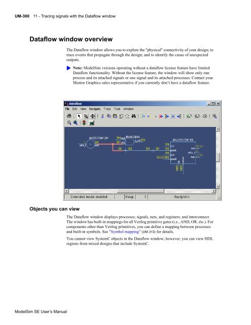
- Page 299: 11 - Tracing signals with the Dataf
- Page 303 and 304: Exploring the connectivity of your
- Page 305 and 306: Zooming and panning Zooming with to
- Page 307 and 308: Tracing the source of an unknown (X
- Page 309 and 310: Finding objects by name in the Data
- Page 311 and 312: Printing on Windows platforms Selec
- Page 313 and 314: Symbol mapping Symbol mapping UM-31
- Page 315 and 316: Configuring window options Configur
- Page 317 and 318: 12 - Profiling performance and memo
- Page 319 and 320: Getting started Memory allocation p
- Page 321 and 322: Enabling the statistical sampling p
- Page 323 and 324: Interpreting profiler data Interpre
- Page 325 and 326: The Call Tree view Viewing profiler
- Page 327 and 328: Viewing profile details Viewing pro
- Page 329 and 330: Integration with Source windows Int
- Page 331 and 332: Reporting profiler results Reportin
- Page 333 and 334: 13 - Measuring code coverage Chapte
- Page 335 and 336: Supported types ModelSim code cover
- Page 337 and 338: Enabling code coverage Enabling cod
- Page 339 and 340: Enabling code coverage UM-339 Next,
- Page 341 and 342: Viewing coverage data in the Source
- Page 343 and 344: Toggle coverage Enabling Toggle cov
- Page 345 and 346: 3 Produce the report with the toggl
- Page 347 and 348: Excluding objects from coverage Exc
- Page 349 and 350: end instance Default filter file Ex
- Page 351 and 352:
XML output Reporting coverage data
- Page 353 and 354:
Instance report with line details R
- Page 355 and 356:
Coverage statistics details Conditi
- Page 357 and 358:
Coverage statistics details UM-357
- Page 359 and 360:
14 - PSL Assertions Chapter content
- Page 361 and 362:
PSL assertion language What are ass
- Page 363 and 364:
Using cover directives Using assert
- Page 365 and 366:
REF2); signal mem_state : memory_st
- Page 367 and 368:
} // Check the write cycle property
- Page 369 and 370:
Multi-clocked properties and defaul
- Page 371 and 372:
Using endpoints in HDL code Example
- Page 373 and 374:
Restrictions Clocking endpoints Usi
- Page 375 and 376:
Compiling and simulating assertions
- Page 377 and 378:
Enabling/disabling failure and pass
- Page 379 and 380:
Setting failure and pass limits Man
- Page 381 and 382:
Reporting on assertions Reporting o
- Page 383 and 384:
15 - Functional coverage with PSL a
- Page 385 and 386:
Compiling and simulating functional
- Page 387 and 388:
Weighting coverage directives Confi
- Page 389 and 390:
Viewing coverage directives in the
- Page 391 and 392:
Reporting functional coverage stati
- Page 393 and 394:
Tag Meaning Understanding aggregate
- Page 395 and 396:
Saving functional coverage data Sav
- Page 397 and 398:
Clearing functional coverage data C
- Page 399 and 400:
16 - C Debug Chapter contents Intro
- Page 401 and 402:
Supported platforms and gdb version
- Page 403 and 404:
Setting breakpoints Setting breakpo
- Page 405 and 406:
Stepping in C Debug Stepping in C D
- Page 407 and 408:
Identifying all registered function
- Page 409 and 410:
Auto find bp versus Auto step mode
- Page 411 and 412:
Debugging functions during elaborat
- Page 413 and 414:
VPI functions in initialization mod
- Page 415 and 416:
C Debug command reference C Debug c
- Page 417 and 418:
17 - Signal Spy Chapter contents In
- Page 419 and 420:
init_signal_driver Call only once S
- Page 421 and 422:
Example library IEEE, modelsim_lib;
- Page 423 and 424:
Arguments Related procedures Limita
- Page 425 and 426:
signal_force Syntax Returns Argumen
- Page 427 and 428:
signal_release Syntax Returns Argum
- Page 429 and 430:
$init_signal_driver Call only once
- Page 431 and 432:
Example `timescale 1 ps / 1 ps modu
- Page 433 and 434:
Related tasks Limitations Example N
- Page 435 and 436:
Related tasks Limitations Example N
- Page 437 and 438:
Example module testbench; reg relea
- Page 439 and 440:
18 - Standard Delay Format (SDF) Ti
- Page 441 and 442:
SDF specification with the GUI Erro
- Page 443 and 444:
Resolving errors VHDL VITAL SDF UM-
- Page 445 and 446:
Examples Optional arguments can be
- Page 447 and 448:
REMOVAL is matched to $removal: SDF
- Page 449 and 450:
Optional conditions Timing check po
- Page 451 and 452:
Interconnect delays Interconnect de
- Page 453 and 454:
Mistaking a component or module nam
- Page 455 and 456:
19 - Value Change Dump (VCD) Files
- Page 457 and 458:
Checkpoint/restore and writing VCD
- Page 459 and 460:
Example 3 — Mixed-HDL design Firs
- Page 461 and 462:
ModelSim VCD commands and VCD tasks
- Page 463 and 464:
A VCD file from source to output VH
- Page 465 and 466:
x) x* x+ x, $end #300 $dumpon 1! 0"
- Page 467 and 468:
Capturing port driver data Supporte
- Page 469 and 470:
Example VCD output from vcd dumppor
- Page 471 and 472:
20 - Tcl and macros (DO files) Chap
- Page 473 and 474:
Tcl commands Tcl commands UM-473 Fo
- Page 475 and 476:
Tcl command syntax UM-475 7 If a wo
- Page 477 and 478:
set command syntax Tcl command synt
- Page 479 and 480:
Variable substitution System comman
- Page 481 and 482:
ModelSim Tcl time commands Conversi
- Page 483 and 484:
Tcl examples This is an example of
- Page 485 and 486:
} if {$windowName == ""} { # Dialog
- Page 487 and 488:
Macros (DO files) Creating DO files
- Page 489 and 490:
set vFilesExist 1 } shift } if {$vh
- Page 491 and 492:
Using the Tcl source command with D
- Page 493 and 494:
The Tcl Debugger Starting the debug
- Page 495 and 496:
Breakpoints The Tcl Debugger UM-495
- Page 497 and 498:
TclPro Debugger TclPro Debugger UM-
- Page 499 and 500:
A - ModelSim GUI changes Appendix c
- Page 501 and 502:
Main window changes UM-501 See "Cus
- Page 503 and 504:
Main window changes UM-503 File > O
- Page 505 and 506:
View menu The View menu has been re
- Page 507 and 508:
Tools menu The 6.0 Main window Tool
- Page 509 and 510:
List window changes File menu The L
- Page 511 and 512:
File menu See "Memory windows" (GR-
- Page 513 and 514:
View menu The Memory window > View
- Page 515 and 516:
Edit menu The Signals window > Edit
- Page 517 and 518:
View menu The Source window > File
- Page 519 and 520:
B - ModelSim variables Appendix con
- Page 521 and 522:
Environment variables Environment v
- Page 523 and 524:
Library mapping with environment va
- Page 525 and 526:
[Library] library path variables Va
- Page 527 and 528:
[vcom] VHDL compiler control variab
- Page 529 and 530:
[vsim] simulator control variables
- Page 531 and 532:
Preference variables located in INI
- Page 533 and 534:
Preference variables located in INI
- Page 535 and 536:
Preference variables located in INI
- Page 537 and 538:
Commonly used INI variables Prefere
- Page 539 and 540:
Force command defaults Preference v
- Page 541 and 542:
Variable precedence Variable preced
- Page 543 and 544:
Special considerations for the now
- Page 545 and 546:
C - Error and warning messages Appe
- Page 547 and 548:
ModelSim message system UM-547 Ther
- Page 549 and 550:
Exit codes The table below describe
- Page 551 and 552:
Miscellaneous messages Miscellaneou
- Page 553 and 554:
Miscellaneous messages UM-553 model
- Page 555 and 556:
VSIM license lost Message text Cons
- Page 557 and 558:
Suggested action Multiply defined s
- Page 559 and 560:
D - Verilog PLI / VPI / DPI Chapter
- Page 561 and 562:
Registering PLI applications Regist
- Page 563 and 564:
Registering VPI applications Exampl
- Page 565 and 566:
Registering DPI applications Regist
- Page 567 and 568:
For Windows only: Run a preliminary
- Page 569 and 570:
32-bit Linux platform Compiling and
- Page 571 and 572:
gcc compiler gcc -c -I//modeltech/i
- Page 573 and 574:
For DPI imports 64-bit IBM RS/6000
- Page 575 and 576:
32-bit Linux platform Compiling and
- Page 577 and 578:
64-bit Solaris platform Compiling a
- Page 579 and 580:
64-bit IBM RS/6000 platform DPI spe
- Page 581 and 582:
Loading shared objects with global
- Page 583 and 584:
VPI example The following example i
- Page 585 and 586:
The PLI callback reason argument Th
- Page 587 and 588:
The sizetf callback function The si
- Page 589 and 590:
Third party PLI applications Third
- Page 591 and 592:
IEEE Std 1364 ACC routines IEEE Std
- Page 593 and 594:
IEEE Std 1364 TF routines IEEE Std
- Page 595 and 596:
SystemVerilog DPI access routines S
- Page 597 and 598:
Verilog-XL compatible routines Veri
- Page 599 and 600:
PLI/VPI tracing The purpose of trac
- Page 601 and 602:
Debugging PLI/VPI/DPI application c
- Page 603 and 604:
E - ModelSim shortcuts Appendix con
- Page 605 and 606:
Main and Source window mouse and ke
- Page 607 and 608:
Keystrokes - UNIX Keystrokes - Wind
- Page 609 and 610:
Wave window mouse and keyboard shor
- Page 611 and 612:
F - System initialization Appendix
- Page 613 and 614:
Environment variables accessed duri
- Page 615 and 616:
Initialization sequence Initializat
- Page 617 and 618:
G - Logic Modeling SmartModels Appe
- Page 619 and 620:
Creating foreign architectures with
- Page 621 and 622:
Vector ports Entity details VHDL Sm
- Page 623 and 624:
SmartModel Windows VHDL SmartModel
- Page 625 and 626:
Verilog SmartModel interface Verilo
- Page 627 and 628:
H - Logic Modeling hardware models
- Page 629 and 630:
Creating foreign architectures with
- Page 631 and 632:
Vector ports Architecture details V
- Page 633 and 634:
End-User License Agreement IMPORTAN
- Page 635 and 636:
COMPLIED WITH THIS AGREEMENT. MENTO
- Page 637 and 638:
Graphics shall only use or disclose
- Page 639 and 640:
Index CR = Command Reference, UM =
- Page 641 and 642:
Stop on quit mode UM-414 C Debug se
- Page 643 and 644:
mem search CR-204 modelsim CR-206 n
- Page 645 and 646:
ange checking in VHDL CR-316, UM-74
- Page 647 and 648:
Add Folder GR-47 C Debug setup GR-9
- Page 649 and 650:
F -f CR-360 F8 function key UM-607
- Page 651 and 652:
Verilog modules UM-125 VHDL subprog
- Page 653 and 654:
Memory window GR-169 GUI changes UM
- Page 655 and 656:
optimizing Verilog designs design o
- Page 657 and 658:
eaders and drivers UM-303 readers c
- Page 659 and 660:
adix specifying for examine CR-163
- Page 661 and 662:
system tasks VCD UM-461 Verilog UM-
- Page 663 and 664:
U -u CR-365 unbound component GR-53
- Page 665 and 666:
library clause UM-64 mixed designs
- Page 667 and 668:
text editing UM-605 windows Active


