- Page 1 and 2: CHARACTERIZATION, MODELING, AND DES
- Page 3 and 4: Abstract For more than 20 years, su
- Page 5 and 6: Acknowledgments This work could not
- Page 7 and 8: Contents Abstract iii Acknowledgmen
- Page 9 and 10: 6 Conclusion 165 6.1 Contributions
- Page 11 and 12: List of Figures 1.1 ESD protection
- Page 13 and 14: 3.32 Simulated 1/∆T vs. time and
- Page 15 and 16: A.65 The output file, bvceo.out, fo
- Page 17 and 18: Chapter 1 Introduction Electrostati
- Page 19 and 20: 1.1. ESD in the Integrated Circuit
- Page 21 and 22: 1.2. Characterizing ESD in Integrat
- Page 23 and 24: 1.3. Protecting Integrated Circuits
- Page 25 and 26: 1.4. Numerical Simulation 9 simulat
- Page 27 and 28: 1.5. Design Methodology 11 process.
- Page 29 and 30: 1.6. Outline and Contributions 13 A
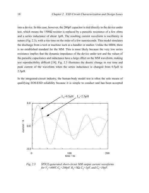
- Page 31 and 32: Chapter 2 ESD Circuit Characterizat
- Page 33: 2.1. Classical ESD Characterization
- Page 37 and 38: 2.2. Transmission Line Pulsing 21 (
- Page 39 and 40: 2.2. Transmission Line Pulsing 23 (
- Page 41 and 42: 2.2. Transmission Line Pulsing 25 I
- Page 43 and 44: 2.2. Transmission Line Pulsing 27 I
- Page 45 and 46: 2.2. Transmission Line Pulsing 29 E
- Page 47 and 48: 2.2. Transmission Line Pulsing 31 w
- Page 49 and 50: 2.2. Transmission Line Pulsing 33 a
- Page 51 and 52: 2.2. Transmission Line Pulsing 35 F
- Page 53 and 54: 2.3. Overview of Protection Circuit
- Page 55 and 56: 2.3. Overview of Protection Circuit
- Page 57 and 58: 2.3. Overview of Protection Circuit
- Page 59 and 60: 2.3. Overview of Protection Circuit
- Page 61 and 62: 2.4. Dependence of Critical MOSFET
- Page 63 and 64: 2.4. Dependence of Critical MOSFET
- Page 65 and 66: 2.5. Design Methodology 49 the subs
- Page 67 and 68: 2.5. Design Methodology 51 The perf
- Page 69 and 70: 2.5. Design Methodology 53 enter se
- Page 71 and 72: Chapter 3 Simulation: Methods and A
- Page 73 and 74: 3.1. Lattice Temperature and Temper
- Page 75 and 76: 3.1. Lattice Temperature and Temper
- Page 77 and 78: 3.1. Lattice Temperature and Temper
- Page 79 and 80: 3.1. Lattice Temperature and Temper
- Page 81 and 82: 3.2. Curve Tracing 65 line (c) in F
- Page 83 and 84: 3.3. Mixed Mode Simulation 67 x n-1
- Page 85 and 86:
3.3. Mixed Mode Simulation 69 V c C
- Page 87 and 88:
3.4. Previous ESD Applications 71 v
- Page 89 and 90:
3.4. Previous ESD Applications 73 I
- Page 91 and 92:
3.5. Extraction of MOSFET I-V Param
- Page 93 and 94:
3.6. Extraction of MOSFET Pf vs. tf
- Page 95 and 96:
3.6. Extraction of MOSFET Pf vs. tf
- Page 97 and 98:
3.6. Extraction of MOSFET Pf vs. tf
- Page 99 and 100:
3.6. Extraction of MOSFET Pf vs. tf
- Page 101 and 102:
3.6. Extraction of MOSFET Pf vs. tf
- Page 103 and 104:
3.7. Simulation of Dielectric Failu
- Page 105 and 106:
3.7. Simulation of Dielectric Failu
- Page 107 and 108:
3.7. Simulation of Dielectric Failu
- Page 109 and 110:
3.7. Simulation of Dielectric Failu
- Page 111 and 112:
Chapter 4 Simulation: Calibration a
- Page 113 and 114:
4.1. Calibration Procedure 97 and t
- Page 115 and 116:
4.1. Calibration Procedure 99 conta
- Page 117 and 118:
4.1. Calibration Procedure 101 4.40
- Page 119 and 120:
4.1. Calibration Procedure 103 Afte
- Page 121 and 122:
4.1. Calibration Procedure 105 past
- Page 123 and 124:
4.1. Calibration Procedure 107 whic
- Page 125 and 126:
4.1. Calibration Procedure 109 simu
- Page 127 and 128:
4.1. Calibration Procedure 111 (a)
- Page 129 and 130:
4.1. Calibration Procedure 113 wher
- Page 131 and 132:
4.1. Calibration Procedure 115 peri
- Page 133 and 134:
4.1. Calibration Procedure 117 simu
- Page 135 and 136:
4.1. Calibration Procedure 119 volt
- Page 137 and 138:
4.2. MOSFET Snapback I-V Results 12
- Page 139 and 140:
4.2. MOSFET Snapback I-V Results 12
- Page 141 and 142:
4.3. Device Failure Results 125 V t
- Page 143 and 144:
4.3. Device Failure Results 127 alr
- Page 145 and 146:
4.3. Device Failure Results 129 act
- Page 147 and 148:
4.3. Device Failure Results 131 (a)
- Page 149 and 150:
4.3. Device Failure Results 133 (a)
- Page 151 and 152:
4.4. Design Example 135 reached, th
- Page 153 and 154:
4.4. Design Example 137 Using value
- Page 155 and 156:
Chapter 5 Design and Optimization o
- Page 157 and 158:
5.1. Methodology 141 5.1 Methodolog
- Page 159 and 160:
5.1. Methodology 143 W L DGS SGS Co
- Page 161 and 162:
5.1. Methodology 145 reaches its pe
- Page 163 and 164:
5.1. Methodology 147 the same withs
- Page 165 and 166:
5.1. Methodology 149 various respon
- Page 167 and 168:
5.1. Methodology 151 needed to desc
- Page 169 and 170:
5.1. Methodology 153 The actual pat
- Page 171 and 172:
5.2. Application 155 To determine h
- Page 173 and 174:
5.3. Analysis 157 are flat, a direc
- Page 175 and 176:
5.3. Analysis 159 assumed to be iso
- Page 177 and 178:
5.4. Optimization 161 Qualitatively
- Page 179 and 180:
5.5. Summary of Design Methodology
- Page 181 and 182:
Chapter 6 Conclusion In the integra
- Page 183 and 184:
6.1. Contributions 167 TLP was show
- Page 185 and 186:
6.2. Future Work 169 most ESD quali
- Page 187 and 188:
6.2. Future Work 171 Significant wo
- Page 189 and 190:
Appendix A Tracer User’s Manual S
- Page 191 and 192:
A.3. CONTROL Card 175 A.3 CONTROL C
- Page 193 and 194:
A.4. FIXED Card 177 A.4 FIXED Card
- Page 195 and 196:
A.5. OPTION Card 179 • DAMP is a
- Page 197 and 198:
A.5. OPTION Card 181 A.5.4 Examples
- Page 199 and 200:
A.6. SOLVE Card 183 if the voltage
- Page 201 and 202:
A.7. Input Deck Specifications 185
- Page 203 and 204:
A.9. Examples 187 column contains c
- Page 205 and 206:
A.9. Examples 189 fixed num = 1 typ
- Page 207 and 208:
A.9. Examples 191 Collector Current
- Page 209 and 210:
A.9. Examples 193 title mes.pis mes
- Page 211 and 212:
A.9. Examples 195 simulator to use.
- Page 213 and 214:
A.9. Examples 197 #Soln #Vctrl Ictr
- Page 215 and 216:
Bibliography [1] T.J. Green and W.K
- Page 217 and 218:
Bibliography 201 [20] C. Duvvury, R
- Page 219 and 220:
Bibliography 203 [42] S.M. Sze, Phy
- Page 221 and 222:
Bibliography 205 [63] R. van Overst