

characterization, modeling, and design of esd protection circuits
characterization, modeling, and design of esd protection circuits
characterization, modeling, and design of esd protection circuits

You also want an ePaper? Increase the reach of your titles
YUMPU automatically turns print PDFs into web optimized ePapers that Google loves.
20 Chapter 2. ESD Circuit Characterization <strong>and</strong> Design Issues<br />
+<br />
V i<br />
-<br />
R i =1MΩ<br />
S<br />
DUT<br />
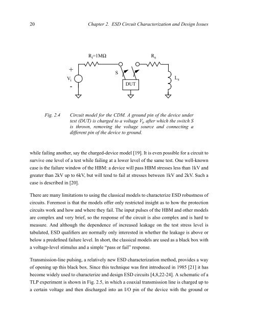
Fig. 2.4 Circuit model for the CDM. A ground pin <strong>of</strong> the device under<br />
test (DUT) is charged to a voltage V i , after which the switch S<br />
is thrown, removing the voltage source <strong>and</strong> connecting a<br />
different pin <strong>of</strong> the device to ground.<br />
while failing another, say the charged-device model [19]. It is even possible for a circuit to<br />
survive one level <strong>of</strong> a test while failing at a lower level <strong>of</strong> the same test. One well-known<br />
case is the failure window <strong>of</strong> the HBM: a device will pass HBM stresses less than 1kV <strong>and</strong><br />
greater than 2kV up to 6kV, but will tend to fail at stresses between 1kV <strong>and</strong> 2kV. Such a<br />
case is described in [20].<br />
There are many limitations to using the classical models to characterize ESD robustness <strong>of</strong><br />
<strong>circuits</strong>. Foremost is that the models <strong>of</strong>fer only restricted insight as to how the <strong>protection</strong><br />
<strong>circuits</strong> work <strong>and</strong> how <strong>and</strong> where they fail. The input pulses <strong>of</strong> the HBM <strong>and</strong> other models<br />
are complex <strong>and</strong> very brief, so the response <strong>of</strong> the circuit is also complex <strong>and</strong> is hard to<br />
measure. And although the dependence <strong>of</strong> increased leakage on the test stress level is<br />
tabulated, ESD qualifiers are normally only interested in whether the leakage is above or<br />
below a predefined failure level. In short, the classical models are used as a black box with<br />
a voltage-level stimulus <strong>and</strong> a simple “pass or fail” response.<br />
Transmission-line pulsing, a relatively new ESD <strong>characterization</strong> method, provides a way<br />
<strong>of</strong> opening up this black box. Since this technique was first introduced in 1985 [21] it has<br />
become widely used to characterize <strong>and</strong> <strong>design</strong> ESD <strong>circuits</strong> [4,8,22-24]. A schematic <strong>of</strong> a<br />
TLP experiment is shown in Fig. 2.5, in which a coaxial transmission line is charged up to<br />
a certain voltage <strong>and</strong> then discharged into an I/O pin <strong>of</strong> the device with the ground or<br />
R s<br />
L s


