- Page 1 and 2:
BSA Flow Software Version 4.10 Inst
- Page 3 and 4:
1. General 1.1 Table of Contents 1.
- Page 5 and 6:
5.5 Optical Calibrated LDA System p
- Page 7 and 8:
7.2.1 Basic principles of phase Dop
- Page 9 and 10:
1.2 Dantec Dynamics Licence Agreeme
- Page 11 and 12:
1.3 Laser safety All equipment usin
- Page 13 and 14:
2. Introduction Congratulations wit
- Page 15 and 16:
2.1.9 Analog Monitor Option 2.1.10
- Page 17 and 18:
2.3.4 Trouble shooting 2.3.5 On-lin
- Page 19 and 20:
3. Installation 3.1 General 3.1.1 P
- Page 21 and 22:
Directory structure CPU usage will
- Page 23 and 24:
3.2.2 Installation as administrator
- Page 25 and 26:
You have the possibility to define
- Page 27 and 28:
Click Next and select the add-ons y
- Page 29 and 30:
Peer-to-peer connection Processor s
- Page 31 and 32:
Click on the Download tab to get th
- Page 33 and 34:
The BSA processor will restart. Thi
- Page 35 and 36:
• If the Game controller needs to
- Page 37 and 38:
Figure 3-2 National Instruments Mea
- Page 39 and 40:
3.7 Third party traverse system To
- Page 41 and 42:
4. The user interface 4.1 Layout Me
- Page 43 and 44:
4. If the mouse pointer was in the
- Page 45 and 46:
4.3 Project explorer shortcuts to t
- Page 47 and 48:
Figure 4-5 Dialog for adding object
- Page 49 and 50:
Using Templates To make a Template,
- Page 51 and 52:
4.6 The tool bar Figure 4-6 the pro
- Page 53 and 54:
Save As... Figure 4-10 the File men
- Page 55 and 56:
Figure 4-11 Save As compressed proj
- Page 57 and 58:
Figure 4-14 the Properties - Summar
- Page 59 and 60:
Figure 4-18 The Select Position dia
- Page 61 and 62:
Options With the Options you get a
- Page 63 and 64:
When Enable error logging is checke
- Page 65 and 66:
The fourth format, Significant Digi
- Page 67 and 68:
The PDA Optical Configuration objec
- Page 69 and 70:
4.7.7 Help menu Figure 4-34 The Hel
- Page 71 and 72:
4.9 Message window • by clicking
- Page 73 and 74:
PM and Bragg cell connections Warni
- Page 75 and 76:
LDA and PDA transmitting optics The
- Page 77 and 78:
Click on OK. Note For fully opaque
- Page 79 and 80:
In the third step, the software con
- Page 81 and 82:
Lightweight Traverse with handbox C
- Page 83 and 84:
57G15 Traverse interface Third part
- Page 85 and 86:
• right-click the Traverse Server
- Page 87 and 88:
4. This brings up the following dia
- Page 89 and 90:
To change a setting, click in the V
- Page 91 and 92:
Figure 4-39 System monitor in auto-
- Page 93 and 94:
14. You have now completed data acq
- Page 95 and 96:
4. Check the Show System Monitor wh
- Page 97 and 98:
. 8. LDA 1 properties are specific
- Page 99 and 100:
11. To monitor the Doppler signals,
- Page 101 and 102:
The axes will automatically rescale
- Page 103 and 104:
Click Acquire. If a complete new re
- Page 105 and 106:
Define the positions that you want
- Page 107 and 108:
Select the type of the files to ope
- Page 109 and 110:
5. Project explorer objects 5.1 Sta
- Page 111 and 112:
Browse to the file you wish to impo
- Page 113 and 114:
For each column, the data type must
- Page 115 and 116:
5.3.1 Output properties Figure 5-4
- Page 117 and 118:
Figure 5-7 The Custom… dialog und
- Page 119 and 120:
Figure 5-8 BSA F/P 30: processor pr
- Page 121 and 122:
Max. acquisition time: The maximum
- Page 123 and 124:
Normal user interface Advanced user
- Page 125 and 126:
Figure 5-11 The Bragg cell connecto
- Page 127 and 128:
LDA 1, 2, . properties: Range and g
- Page 129 and 130:
5.3.4 System monitor It frequently
- Page 131 and 132:
Scope: Burst spectrum display Recor
- Page 133 and 134:
Overlaid Graphs: used to show the b
- Page 135 and 136:
Uncheck the Use default bindings bo
- Page 137 and 138:
The calibration data are stored in
- Page 139 and 140:
5.6.1 PDA beam system The Beam syst
- Page 141 and 142:
Figure 5-24: Fringe direction setti
- Page 143 and 144:
5.6.4 Medium properties Medium name
- Page 145 and 146:
Software max. limit in mm.: Self ex
- Page 147 and 148:
The default address of the National
- Page 149 and 150:
Traverse coordinates of a datum poi
- Page 151 and 152:
5.7.8 Traverse Mesh generator If yo
- Page 153 and 154:
Regions Figure 5-39 Motion pattern,
- Page 155 and 156:
Warning Please observe strict secur
- Page 157 and 158:
5.9 Export Figure 5-40 Data-sources
- Page 159 and 160:
If multiple positions are exported
- Page 161 and 162:
5.9.3 Selected columns 5.9.4 Binary
- Page 163 and 164:
Data C Headers Programming Examples
- Page 165 and 166:
char filename[256] = {0}; strcpy(fi
- Page 167 and 168:
Range means that the filter will ap
- Page 169 and 170:
5.11.1 Data Properties Note that th
- Page 171 and 172:
Figure 5-54. Size histogram (left)
- Page 173 and 174:
Figure 5-57. Velocity distribution
- Page 175 and 176:
Figure 5-58 list output of 1D PDA d
- Page 177 and 178:
The next selection in the context m
- Page 179 and 180: 5.13.2 Objects under Merge object A
- Page 181 and 182: N−1 Mean u ∑ ηiui = i= 0 N−1
- Page 183 and 184: Cross-moments The property Cross-mo
- Page 185 and 186: The calculation of ε fails if Umea
- Page 187 and 188: Figure 5-71 General properties of t
- Page 189 and 190: An alternative geometry of a 3D LDA
- Page 191 and 192: Figure 5-75: FiberPDA phase plot. A
- Page 193 and 194: 5.16.3 Display properties The defau
- Page 195 and 196: The output quantities of the diamet
- Page 197 and 198: 6. Options and Add-ons This chapter
- Page 199 and 200: 6.1 Advanced Graphics Add-on The ma
- Page 201 and 202: Figure 6-2 The Tools-Options-Output
- Page 203 and 204: Figure 6-5 Scale properties for 2D
- Page 205 and 206: Property group ‘Display’ Also t
- Page 207 and 208: 6.1.3 2D Plot [m/s] 36 34 32 The 2D
- Page 209 and 210: 6.1.4 2D Histogram For off-line use
- Page 211 and 212: Configuring the 2D Histogram The co
- Page 213 and 214: Configuring the 3D Plot Figure 6-21
- Page 215 and 216: Figure 6-23 “Interpolate bin” s
- Page 217 and 218: Property group ‘Data’ Figure 6-
- Page 219 and 220: Coordinate shown on Intercepts the
- Page 221 and 222: LDA1-Mean [m/ s] -2,00 -3,00 -4,00
- Page 223 and 224: Figure 6-32 Properties of the Vecto
- Page 225 and 226: Figure 6-33 shows a velocity vector
- Page 227 and 228: 6.1.9 Exporting plots Copying a plo
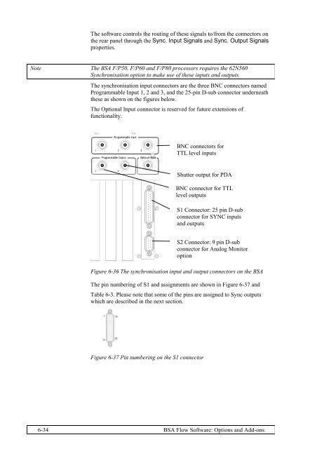
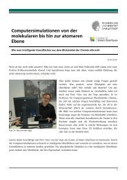
- Page 229: 6.2 Synchronisation Option 6.2.1 In
- Page 233 and 234: 6.2.5 Sync. Output Signals properti
- Page 235 and 236: Outputs Figure 6-40 Differential sy
- Page 237 and 238: Figure 6-42 Cyclic phenomena in the
- Page 239 and 240: Cycle length The property Cycle len
- Page 241 and 242: It allows to define the number of b
- Page 243 and 244: Note It is not possible to have 0 a
- Page 245 and 246: Figure 6-47: Output data from the c
- Page 247 and 248: performed prior to phase sorting yo
- Page 249 and 250: Figure 6-51 Properties of the spect
- Page 251 and 252: Blocking Using the FFT-approach to
- Page 253 and 254: 1,2 1,0 0,8 0,6 0,4 0,2 Weight fact
- Page 255 and 256: Output from the Spectrum object The
- Page 257 and 258: 6.4.2 Advanced Spectrum object Load
- Page 259 and 260: To evaluate the new algorithm, comp
- Page 261 and 262: 6.4.3 Correlation object Conclusion
- Page 263 and 264: 20 16 12 8 4 0 0.0 0.2 0.4 0.6 0.8
- Page 265 and 266: Time The first column of the output
- Page 267 and 268: The Protocol Figure 6-67: Generic t
- Page 269 and 270: How to Use the Initialisation Strin
- Page 271 and 272: Figure 6-69: Traverse File option i
- Page 273 and 274: Properties Output from MATLAB engin
- Page 275 and 276: Result window Script Hides and disp
- Page 277 and 278: 6.6.2 Calculation object from to
- Page 279 and 280: Tip To combine calculated data and
- Page 281 and 282:
max var. max of all arguments sum v
- Page 283 and 284:
6.7.3 Software set-up Once A/D-hard
- Page 285 and 286:
Figure 6-76 BSA F/P application win
- Page 287 and 288:
6.7.7 Analog input specifications J
- Page 289 and 290:
6.8.1 Installation 6.8.2 Hardware c
- Page 291 and 292:
Figure 6-85 BSA F/P application win
- Page 293 and 294:
6.9.1 Required hardware 6.9.2 Calib
- Page 295 and 296:
2. Select Parameter Input 3. The fo
- Page 297 and 298:
B. Select Advanced Curve fitting an
- Page 299 and 300:
6.10 Mobile system Monitor option T
- Page 301 and 302:
7. Reference guide 7.1 Theory of La
- Page 303 and 304:
Doppler effect d0 R(z) Figure 7-1 L
- Page 305 and 306:
es e2 e1 U Figure 7-3 Scattering of
- Page 307 and 308:
Measuring volume proportional to pa
- Page 309 and 310:
Laser fI Beam splitter As indicated
- Page 311 and 312:
7.1.6 Frequency shift • Reduce th
- Page 313 and 314:
As long as the particle velocity do
- Page 315 and 316:
7.1.7 Signals The primary result of
- Page 317 and 318:
7.1.8 Seeding Seeding as flow field
- Page 319 and 320:
150 90 180 0 180 0 180 0 210 120 24
- Page 321 and 322:
7.2 Theory of Phase Doppler Anemome
- Page 323 and 324:
D is the particle diameter. βi is
- Page 325 and 326:
For reflection (Equation 7-16) The
- Page 327 and 328:
Figure 7-21: The effect of changing
- Page 329 and 330:
This is the principle of the spheri
- Page 331 and 332:
The trajectory effect The slit effe
- Page 333 and 334:
Figure 7-28:The DualPDA as a combin
- Page 335 and 336:
Figure 7-31: Reflection and refract
- Page 337 and 338:
Characteristic scattering angles At
- Page 339 and 340:
⎛ ϕ ⎞ ϕ2 = 4arcsin⎜ ⎟ −
- Page 341 and 342:
Figure 7-36: The critical angle con
- Page 343 and 344:
Using side scatter (reflected light
- Page 345 and 346:
Mask Front Lens Eye-piece Spatial f
- Page 347 and 348:
Alignment of the eyepiece The focus
- Page 349 and 350:
This is often not necessary in 1D a
- Page 351 and 352:
For both orientations of polarizati
- Page 353 and 354:
Figure 7-46. The effect of changing
- Page 355 and 356:
Table of characteristic angles Defi
- Page 357 and 358:
n rel ϕ c1 ϕ b0 ϕ c2 ϕ b2 ϕ r2
- Page 359 and 360:
n rel ϕ c1 ϕ b0 ϕ c2 ϕ b2 ϕ r2
- Page 361 and 362:
n rel ϕ c1 ϕ b0 ϕ c2 ϕ b2 ϕ r2
- Page 363 and 364:
n rel ϕ c1 ϕ b0 ϕ c2 ϕ b2 ϕ r2
- Page 365 and 366:
Choice of wavelength Choice of mask
- Page 367 and 368:
Choice of wavelength and focal leng
- Page 369 and 370:
Choice of polarization Choice of sc
- Page 371 and 372:
Focal length Transmitter (FiberFlow
- Page 373 and 374:
Polarization ring Fixing screw Push
- Page 375 and 376:
Aperture plates The particle size r
- Page 377 and 378:
Tighten the cable securely at each
- Page 379 and 380:
Disconnect the receiving fiber V1 f
- Page 381 and 382:
Step by step procedure Phase-Dopple
- Page 383 and 384:
Lower half: The lower half of the b
- Page 385 and 386:
Recommended acceptance angles of th
- Page 387 and 388:
7.7.4 Air bubble in freon Character
- Page 389 and 390:
7.7.6 Bubble of air in diesel oil C
- Page 391 and 392:
7.7.8 Glass sphere in water Charact
- Page 393 and 394:
7.7.10 Latex sphere in water Charac
- Page 395 and 396:
Blocking increases calculation spee
- Page 397 and 398:
In this particular example we get:
- Page 399 and 400:
7.9 Moments (one-time statistics) 7
- Page 401 and 402:
1 = N Mean D mean ui (7-31) N ∑
- Page 403 and 404:
Software implementation Updating me
- Page 405 and 406:
u v 2 2 = = ∑ ∑ tU tV 2 2 − 2
- Page 407 and 408:
(histogram properties). ni is the n
- Page 409 and 410:
volume is calculated for the class
- Page 411 and 412:
D30 The volume mean diameter is cal
- Page 413 and 414:
Three further factors are however i
- Page 415 and 416:
d e ln 2 max 2 V do ∗ Vt = ( 7-48
- Page 417 and 418:
Diameter bins The number of diamete
- Page 419 and 420:
Trajectory dependent detection area
- Page 421 and 422:
Corrected particle Max d e ( Di ) C
- Page 423 and 424:
Integral time-scale τI Definition
- Page 425 and 426:
The mean values of u(t) and v(t) ar
- Page 427 and 428:
Low pass filtering & Step noise Obv
- Page 429 and 430:
fc ≡ t 1 2 ∆ If the true signal
- Page 431 and 432:
Estimator bias Estimator variance S
- Page 433 and 434:
-again S’(f) is used to distingui
- Page 435 and 436:
Zero padding Often the sampling per
- Page 437:
As an example the Hanning window is
- Page 440 and 441:
The Explorer window will now look s
- Page 442 and 443:
8.2.2 Peer-to-Peer Configuration Co
- Page 444 and 445:
. High Voltage or Figure 8-3: Calib
- Page 446 and 447:
Invalid particles in the corners Th
- Page 448 and 449:
Gaussain beam effect The following
- Page 450 and 451:
To check for connection, right-clic