- Page 1 and 2:
TC.GSS Grid-tie Source Sink Regatro
- Page 3 and 4:
Manual - TopCon TC.GSS Manufacturer
- Page 5 and 6:
Manual - TopCon TC.GSS Using the ma
- Page 7 and 8:
Manual - TopCon TC.GSS Table of con
- Page 9 and 10:
Manual - TopCon TC.GSS General Tabl
- Page 11 and 12:
Manual - TopCon TC.GSS 1. Product d
- Page 13 and 14:
Manual - TopCon TC.GSS Mechanical d
- Page 15 and 16:
Manual - TopCon TC.GSS 1.6. Positio
- Page 17 and 18:
Manual - TopCon TC.GSS Position of
- Page 19 and 20:
Manual - TopCon TC.GSS 2. Safety Ge
- Page 21 and 22:
Manual - TopCon TC.GSS Categorisati
- Page 23 and 24:
Manual - TopCon TC.GSS Categorisati
- Page 25 and 26:
Manual - TopCon TC.GSS 2.2.5. Trans
- Page 27 and 28:
Manual - TopCon TC.GSS Categorisati
- Page 29 and 30:
Manual - TopCon TC.GSS Instructions
- Page 31 and 32:
Manual - TopCon TC.GSS Controls and
- Page 33 and 34:
Manual - TopCon TC.GSS 4.2. Operati
- Page 35 and 36:
Manual - TopCon TC.GSS Operating mo
- Page 37 and 38:
Manual - TopCon TC.GSS Operating mo
- Page 39 and 40:
Manual - TopCon TC.GSS Operating mo
- Page 41 and 42:
Manual - TopCon TC.GSS Single devic
- Page 43 and 44:
Manual - TopCon TC.GSS Single devic
- Page 45 and 46:
Manual - TopCon TC.GSS Single devic
- Page 47 and 48:
Manual - TopCon TC.GSS Single devic
- Page 49 and 50:
Manual - TopCon TC.GSS Single devic
- Page 51 and 52:
Manual - TopCon TC.GSS Device state
- Page 53 and 54:
Manual - TopCon TC.GSS Single devic
- Page 55 and 56:
Manual - TopCon TC.GSS Single devic
- Page 57 and 58:
Manual - TopCon TC.GSS Multi-unit s
- Page 59 and 60:
Manual - TopCon TC.GSS Multi-unit s
- Page 61 and 62: Manual - TopCon TC.GSS Multi-unit s
- Page 63 and 64: Manual - TopCon TC.GSS Multi-unit s
- Page 65 and 66: Manual - TopCon TC.GSS Multi-unit s
- Page 67 and 68: Manual - TopCon TC.GSS Multi-unit s
- Page 69 and 70: Manual - TopCon TC.GSS 5. Options a
- Page 71 and 72: Manual - TopCon TC.GSS 5.2. Hardwar
- Page 73 and 74: Manual - TopCon TC.GSS CAUTION Opti
- Page 75 and 76: Manual - TopCon TC.GSS Options and
- Page 77 and 78: Manual - TopCon TC.GSS Options and
- Page 79 and 80: Manual - TopCon TC.GSS Options and
- Page 81 and 82: Manual - TopCon TC.GSS 5.3. Softwar
- Page 83 and 84: Manual - TopCon TC.GSS Options and
- Page 85 and 86: Manual - TopCon TC.GSS The gradient
- Page 87 and 88: Manual - TopCon TC.GSS Options and
- Page 89 and 90: Manual - TopCon TC.GSS Options and
- Page 91 and 92: Manual - TopCon TC.GSS Options and
- Page 93 and 94: Manual - TopCon TC.GSS Options and
- Page 95 and 96: Manual - TopCon TC.GSS 5.4.8. TC-Et
- Page 97 and 98: Manual - TopCon TC.GSS Options and
- Page 99 and 100: Manual - TopCon TC.GSS Options and
- Page 101 and 102: Manual - TopCon TC.GSS Options and
- Page 103 and 104: Manual - TopCon TC.GSS Options and
- Page 105 and 106: Manual - TopCon TC.GSS Installation
- Page 107 and 108: Manual - TopCon TC.GSS Cooling Inst
- Page 109 and 110: Manual - TopCon TC.GSS 6.2. Commiss
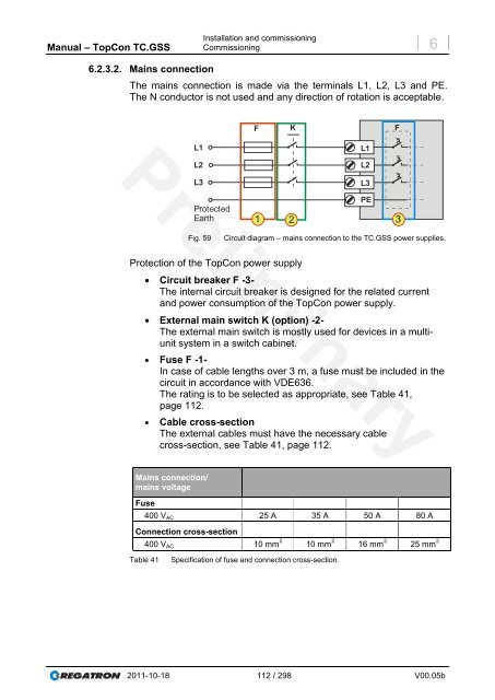
- Page 111: Manual - TopCon TC.GSS Installation
- Page 115 and 116: Manual - TopCon TC.GSS Installation
- Page 117 and 118: Manual - TopCon TC.GSS 6.3.2.4. Fun
- Page 119 and 120: Manual - TopCon TC.GSS 7. Device op
- Page 121 and 122: Manual - TopCon TC.GSS Analogue int
- Page 123 and 124: Manual - TopCon TC.GSS Analogue int
- Page 125 and 126: Manual - TopCon TC.GSS Analogue int
- Page 127 and 128: Manual - TopCon TC.GSS Analogue int
- Page 129 and 130: Manual - TopCon TC.GSS Analogue int
- Page 131 and 132: Manual - TopCon TC.GSS 7.3. HMI and
- Page 133 and 134: Manual - TopCon TC.GSS Multi-unit s
- Page 135 and 136: Manual - TopCon TC.GSS 7.3.4.2. HMI
- Page 137 and 138: Manual - TopCon TC.GSS HMI and RCU
- Page 139 and 140: Manual - TopCon TC.GSS Operation of
- Page 141 and 142: Manual - TopCon TC.GSS System scree
- Page 143 and 144: Manual - TopCon TC.GSS System setti
- Page 145 and 146: Manual - TopCon TC.GSS CAUTION Oper
- Page 147 and 148: Manual - TopCon TC.GSS Operation of
- Page 149 and 150: Manual - TopCon TC.GSS Operation of
- Page 151 and 152: Manual - TopCon TC.GSS Operation of
- Page 153 and 154: Manual - TopCon TC.GSS Limit settin
- Page 155 and 156: Manual - TopCon TC.GSS 7.3.5. Troub
- Page 157 and 158: Manual - TopCon TC.GSS 7.4. TopCont
- Page 159 and 160: Manual - TopCon TC.GSS No CD-ROM dr
- Page 161 and 162: Manual - TopCon TC.GSS Installation
- Page 163 and 164:
Manual - TopCon TC.GSS TopControl -
- Page 165 and 166:
Manual - TopCon TC.GSS TopControl a
- Page 167 and 168:
Manual - TopCon TC.GSS TopControl a
- Page 169 and 170:
Manual - TopCon TC.GSS 7.4.7.2. Men
- Page 171 and 172:
Manual - TopCon TC.GSS Setting the
- Page 173 and 174:
Manual - TopCon TC.GSS 7.4.7.3. Men
- Page 175 and 176:
Manual - TopCon TC.GSS 7.4.8.1. Tab
- Page 177 and 178:
Manual - TopCon TC.GSS TopControl a
- Page 179 and 180:
Manual - TopCon TC.GSS TopControl a
- Page 181 and 182:
Manual - TopCon TC.GSS TopControl a
- Page 183 and 184:
Manual - TopCon TC.GSS 7.4.8.3. Tab
- Page 185 and 186:
Manual - TopCon TC.GSS TopControl a
- Page 187 and 188:
Manual - TopCon TC.GSS TopControl a
- Page 189 and 190:
Manual - TopCon TC.GSS Manual trigg
- Page 191 and 192:
Manual - TopCon TC.GSS TopControl a
- Page 193 and 194:
Manual - TopCon TC.GSS TopControl a
- Page 195 and 196:
Manual - TopCon TC.GSS TopControl a
- Page 197 and 198:
Manual - TopCon TC.GSS Creating AAP
- Page 199 and 200:
Manual - TopCon TC.GSS 7.4.8.4. Tab
- Page 201 and 202:
Manual - TopCon TC.GSS Scope displa
- Page 203 and 204:
Manual - TopCon TC.GSS 4 TopControl
- Page 205 and 206:
Manual - TopCon TC.GSS 8 7 6 TopCon
- Page 207 and 208:
Manual - TopCon TC.GSS “Select si
- Page 209 and 210:
Manual - TopCon TC.GSS TopControl a
- Page 211 and 212:
Manual - TopCon TC.GSS TopControl a
- Page 213 and 214:
Manual - TopCon TC.GSS Control grou
- Page 215 and 216:
Manual - TopCon TC.GSS TopControl a
- Page 217 and 218:
Manual - TopCon TC.GSS TopControl a
- Page 219 and 220:
Manual - TopCon TC.GSS 7.4.8.5. Tab
- Page 221 and 222:
Manual - TopCon TC.GSS TopControl a
- Page 223 and 224:
Manual - TopCon TC.GSS TopControl a
- Page 225 and 226:
Manual - TopCon TC.GSS TopControl a
- Page 227 and 228:
Manual - TopCon TC.GSS TopControl a
- Page 229 and 230:
Manual - TopCon TC.GSS TopControl a
- Page 231 and 232:
Manual - TopCon TC.GSS CAUTION 7.4.
- Page 233 and 234:
Manual - TopCon TC.GSS CAUTION 7.4.
- Page 235 and 236:
Manual - TopCon TC.GSS CAUTION 7.4.
- Page 237 and 238:
Manual - TopCon TC.GSS Parameter li
- Page 239 and 240:
Manual - TopCon TC.GSS Filtering an
- Page 241 and 242:
Manual - TopCon TC.GSS Handling gri
- Page 243 and 244:
Manual - TopCon TC.GSS 7.4.8.11. Ta
- Page 245 and 246:
Manual - TopCon TC.GSS TopControl a
- Page 247 and 248:
Manual - TopCon TC.GSS 7.4.8.12. Ta
- Page 249 and 250:
Manual - TopCon TC.GSS 8. Maintenan
- Page 251 and 252:
Manual - TopCon TC.GSS CAUTION 8.2.
- Page 253 and 254:
Manual - TopCon TC.GSS System infor
- Page 255 and 256:
Manual - TopCon TC.GSS Device hardw
- Page 257 and 258:
Manual - TopCon TC.GSS Support Prod
- Page 259 and 260:
Manual - TopCon TC.GSS 9.6. Device
- Page 261 and 262:
Manual - TopCon TC.GSS Support Disp
- Page 263 and 264:
Manual - TopCon TC.GSS 10.1.2. Leak
- Page 265 and 266:
Manual - TopCon TC.GSS Times Starti
- Page 267 and 268:
Manual - TopCon TC.GSS Appendix Tec
- Page 269 and 270:
Manual - TopCon TC.GSS Appendix Tec
- Page 271 and 272:
Manual - TopCon TC.GSS Appendix Tec
- Page 273 and 274:
Manual - TopCon TC.GSS Appendix Tec
- Page 275 and 276:
Manual - TopCon TC.GSS 10.2. Error
- Page 277 and 278:
Manual - TopCon TC.GSS Appendix Err
- Page 279 and 280:
Manual - TopCon TC.GSS Appendix Err
- Page 281 and 282:
Manual - TopCon TC.GSS Appendix Err
- Page 283 and 284:
Manual - TopCon TC.GSS Appendix Err
- Page 285 and 286:
Manual - TopCon TC.GSS Appendix Err
- Page 287 and 288:
Manual - TopCon TC.GSS Appendix Err
- Page 289 and 290:
Manual - TopCon TC.GSS Appendix Err
- Page 291 and 292:
Manual - TopCon TC.GSS Group error:
- Page 293 and 294:
Manual - TopCon TC.GSS Appendix Err
- Page 295 and 296:
Manual - TopCon TC.GSS TCP_Certific
- Page 297 and 298:
Manual - TopCon TC.GSS 11. Index an