

Manual
Manual
Manual

You also want an ePaper? Increase the reach of your titles
YUMPU automatically turns print PDFs into web optimized ePapers that Google loves.
<strong>Manual</strong> – TopCon TC.GSS<br />
TopControl application<br />
Tab – <br />
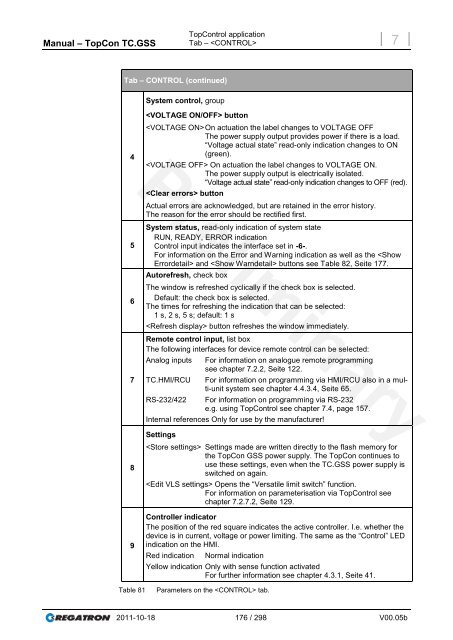
Tab – CONTROL (continued)<br />
4<br />
5<br />
6<br />
7<br />
8<br />
9<br />
System control, group<br />
button<br />
On actuation the label changes to VOLTAGE OFF<br />
The power supply output provides power if there is a load.<br />
“Voltage actual state” read-only indication changes to ON<br />
(green).<br />
On actuation the label changes to VOLTAGE ON.<br />
The power supply output is electrically isolated.<br />
“Voltage actual state” read-only indication changes to OFF (red).<br />
button<br />
Actual errors are acknowledged, but are retained in the error history.<br />
The reason for the error should be rectified first.<br />
System status, read-only indication of system state<br />
RUN, READY, ERROR indication<br />
Control input indicates the interface set in -6-.<br />
For information on the Error and Warning indication as well as the and buttons see Table 82, Seite 177.<br />
Autorefresh, check box<br />
The window is refreshed cyclically if the check box is selected.<br />
Default: the check box is selected.<br />
The times for refreshing the indication that can be selected:<br />
1 s, 2 s, 5 s; default: 1 s<br />
button refreshes the window immediately.<br />
Remote control input, list box<br />
The following interfaces for device remote control can be selected:<br />
Analog inputs For information on analogue remote programming<br />
see chapter 7.2.2, Seite 122.<br />
TC.HMI/RCU For information on programming via HMI/RCU also in a multi-unit<br />
system see chapter 4.4.3.4, Seite 65.<br />
RS-232/422 For information on programming via RS-232<br />
e.g. using TopControl see chapter 7.4, page 157.<br />
Internal references Only for use by the manufacturer!<br />
Settings<br />
Settings made are written directly to the flash memory for<br />
the TopCon GSS power supply. The TopCon continues to<br />
use these settings, even when the TC.GSS power supply is<br />
switched on again.<br />
Opens the “Versatile limit switch” function.<br />
For information on parameterisation via TopControl see<br />
chapter 7.2.7.2, Seite 129.<br />
Controller indicator<br />
The position of the red square indicates the active controller. I.e. whether the<br />
device is in current, voltage or power limiting. The same as the “Control” LED<br />
indication on the HMI.<br />
Red indication Normal indication<br />
Yellow indication Only with sense function activated<br />
For further information see chapter 4.3.1, Seite 41.<br />
Table 81 Parameters on the tab.<br />
2011-10-18 176 / 298 V00.05b<br />
7