

Manual - 8500A Series Peak Power Meter - Giga-tronics
Manual - 8500A Series Peak Power Meter - Giga-tronics
Manual - 8500A Series Peak Power Meter - Giga-tronics

You also want an ePaper? Increase the reach of your titles
YUMPU automatically turns print PDFs into web optimized ePapers that Google loves.
<strong>Series</strong> <strong>8500A</strong> <strong>Peak</strong> <strong>Power</strong> <strong>Meter</strong>s<br />
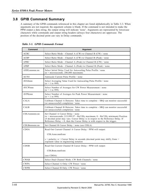
3.8 GPIB Command Summary<br />
A summary of the GPIB commands referenced in this chapter are listed alphabetically in Table 3-3. When<br />
arguments are not required, the argument column is blank. If the command is not intended to make the<br />
PPM output a data string, the output string will indicate ’none’. Arguments are represented by lowercase<br />
characters while commands and output string headers (always four characters) are uppercase. The<br />
position of the decimal point can vary in Delay commands.<br />
Table 3-3. GPIB Commands Format<br />
Command<br />
ACBC<br />
ACBP<br />
APBC<br />
APBP<br />
ASDLnnnnnn.nn<br />
AUTO<br />
AVASnnn<br />
AVCWnnn<br />
AVPKnnn<br />
CALA<br />
CALB<br />
CDLAnnnnnn.nn<br />
CDLBnnnnnn.nn<br />
CDOA<br />
Argument<br />
Select Ratio Mode - Channel A (CW) to Channel B (CW) / none<br />
Select Ratio Mode - Channel A (CW) to Channel B (<strong>Peak</strong>) / none<br />
Select Ratio Mode - Channel A (<strong>Peak</strong>) to Channel B (CW) / none<br />
Select Ratio Mode - Channel A (<strong>Peak</strong>) to Channel B (<strong>Peak</strong>) / none<br />
Select Initial Delay Used for Autoscaling Pulse Profile / none<br />
(n = microseconds; 200,000 maximum)<br />
Autoscale Current Pulse Profile / none<br />
Select Averaging Value Used for Autoscaling Pulse Profile / none<br />
(n = 1 to 999)<br />
Select Number of Averages for CW <strong>Power</strong> Measurement / none<br />
(n = 1 to 999)<br />
Select Number of Averages for <strong>Peak</strong> <strong>Power</strong> Measurement / none<br />
(n = 1 to 999)<br />
Calibrate Channel A Detector. Takes time to complete - SRQ can monitor successful<br />
(or unsuccessful) completion / none<br />
Calibrate Channel B Detector. Takes time to complete - SRQ can monitor successful<br />
(or unsuccessful) completion / none<br />
Set Channel A Cursor Delay / none<br />
(n = microseconds; 213,999.97 - Ref Dly maximum; 0 - Ref Dly minimum) Position<br />
of decimal point may vary. Cursor Delay is in respect to the Reference Delay. If<br />
Reference Delay = 0, then the Cursor Delay is with respect to the trigger.<br />
Set Channel B Cursor Delay / none (see CDLA)<br />
Read Out Current Channel A Cursor Delay / PPM will output:<br />
CDLAsnn.nnnEsnn<br />
s = polarity; n = Cursor Delay in seconds (decimal point may shift); Esnn =<br />
exponent value in engineering notation<br />
CDOB<br />
Read Out Current Channel B Cursor Delay / PPM will output:<br />
CDLBsnn.nnnEsnn<br />
(see CDOA)<br />
CWAB<br />
CWPA<br />
CWPB<br />
Select Dual Channel Mode: CW Both Channels / none<br />
Select Channel A Only: CW <strong>Power</strong> / none<br />
Select Channel B Only: CW <strong>Power</strong> / none<br />
3-44 <strong>Manual</strong> No. 20790, Rev C, November 1998<br />
Superceded by Revision D, March 2009


