

Manual - 8500A Series Peak Power Meter - Giga-tronics
Manual - 8500A Series Peak Power Meter - Giga-tronics
Manual - 8500A Series Peak Power Meter - Giga-tronics

Create successful ePaper yourself
Turn your PDF publications into a flip-book with our unique Google optimized e-Paper software.
<strong>Series</strong> <strong>8500A</strong> <strong>Peak</strong> <strong>Power</strong> <strong>Meter</strong>s<br />
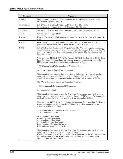
Command<br />
Argument<br />
STORnn<br />
TRGAsnn.nn<br />
TRGBsnn.nn<br />
TRGE<br />
Store Current PPM Settings in Non-Volatile Set-Up Memory Number n / none<br />
(n = number between 1 and 10)<br />
Select Channel A Internal Trigger and Set Level in dBm / none<br />
(s = polarity; n = trigger level - +16 dBm max -20 dBm min)<br />
Select Channel B Internal Trigger and Set Level in dBm / none (See TRGA)<br />
Select External Trigger Mode / none<br />
UNDD Disable PPM SRQ for Underrange Conditions. See Service Requests in Section 3.4 /<br />
none<br />
UNDE<br />
UPDC<br />
Enable PPM SRQ for Underrange Conditions. An SRQ will be generated if the<br />
power level measurement data is below the level set by MINP / none<br />
Select Update Data Continuously Output Mode. The PPM will output a continuous<br />
stream of power measurement data points separated by commas. Every time the PPM<br />
receives a trigger a new data point is added to the stream. The formats described<br />
below can occur.<br />
When using the FREQ, DCFA (A Cal Factor), DCFB (B Cal Factor), or FPRV (Rear<br />
Panel Frequency Input) methods for detector frequency response correction, the<br />
PPM’s Linear Mode data output string for channel A will be:<br />
PWRAnn.nnEsnn,PWRAnn.nnEsnn,PWRAnn.nnEsnn<br />
(n = linear power in Watts; Esnn = exponent)<br />
This example shows a data string for 3 triggers. Subsequent triggers will produce<br />
more data points separated by commas in the form of PWRAnn.nnEsnn. For<br />
channel B the header before the data points would be PRWB instead of PWRA.<br />
The PPM’s dBm Mode output for channel A would be:<br />
DBMAsnnn.nn,DBMAsnnn.nn,DBMAsnnn.nn<br />
(s = polarity; n = dBm)<br />
This example shows a data stream for 3 triggers. Subsequent triggers will produce<br />
more data points separated by commas in the form of DBMAsnn.nn. For channel B<br />
the header before the data points would be DBMB instead of BDMA.<br />
When using the FPVO (Rear Panel Frequency Input and Output) method for detector<br />
frequency response correction, the PPM’s Linear Mode data output string for<br />
channel A will be in the form:<br />
PWRAmm.mmEsee,FRQAfff.ffE+09,PWRAnn.nn<br />
Esee,FRQAggg.ggE+09<br />
(m = first power data point;<br />
f = first frequency data point;<br />
n = second power data point;<br />
g = second frequency data point;<br />
Esee = exponent for power in Watts;<br />
E+09 indicates frequency is in GHz)<br />
This example shows a data stream for 2 triggers. Subsequent triggers will produce<br />
more data points separated by commas in the form of<br />
PWRAnn.nnEsnn,FRQAfff.ffE+09. If the PPM is in channel B the headers before the<br />
data points would be PWRB and FRQB. See preceding NOTE for description<br />
of dBm header and data formats.<br />
3-50 <strong>Manual</strong> No. 20790, Rev C, November 1998<br />
Superceded by Revision D, March 2009


