

Manual - 8500A Series Peak Power Meter - Giga-tronics
Manual - 8500A Series Peak Power Meter - Giga-tronics
Manual - 8500A Series Peak Power Meter - Giga-tronics

You also want an ePaper? Increase the reach of your titles
YUMPU automatically turns print PDFs into web optimized ePapers that Google loves.
<strong>Series</strong> <strong>8500A</strong> <strong>Peak</strong> <strong>Power</strong> <strong>Meter</strong>s<br />
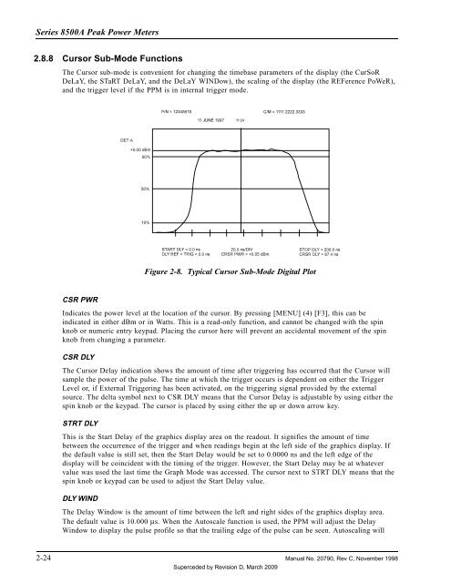
2.8.8 Cursor Sub-Mode Functions<br />
The Cursor sub-mode is convenient for changing the timebase parameters of the display (the CurSoR<br />
DeLaY, the STaRT DeLaY, and the DeLaY WINDow), the scaling of the display (the REFerence PoWeR),<br />
and the trigger level if the PPM is in internal trigger mode.<br />
Figure 2-8. Typical Cursor Sub-Mode Digital Plot<br />
CSR PWR<br />
Indicates the power level at the location of the cursor. By pressing [MENU] (4) [F3], this can be<br />
indicated in either dBm or in Watts. This is a read-only function, and cannot be changed with the spin<br />
knob or numeric entry keypad. Placing the cursor here will prevent an accidental movement of the spin<br />
knob from changing a parameter.<br />
CSR DLY<br />
The Cursor Delay indication shows the amount of time after triggering has occurred that the Cursor will<br />
sample the power of the pulse. The time at which the trigger occurs is dependent on either the Trigger<br />
Level or, if External Triggering has been activated, on the triggering signal provided by the external<br />
source. The delta symbol next to CSR DLY means that the Cursor Delay is adjustable by using either the<br />
spin knob or the keypad. The cursor is placed by using either the up or down arrow key.<br />
STRT DLY<br />
This is the Start Delay of the graphics display area on the readout. It signifies the amount of time<br />
between the occurrence of the trigger and when readings begin at the left side of the graphics display. If<br />
the default value is still set, then the Start Delay would be set to 0.0000 ns and the left edge of the<br />
display will be coincident with the timing of the trigger. However, the Start Delay may be at whatever<br />
value was used the last time the Graph Mode was accessed. The cursor next to STRT DLY means that the<br />
spin knob or keypad can be used to adjust the Start Delay value.<br />
DLY WIND<br />
The Delay Window is the amount of time between the left and right sides of the graphics display area.<br />
The default value is 10.000 µs. When the Autoscale function is used, the PPM will adjust the Delay<br />
Window to display the pulse profile so that the trailing edge of the pulse can be seen. Autoscaling will<br />
2-24 <strong>Manual</strong> No. 20790, Rev C, November 1998<br />
Superceded by Revision D, March 2009


