

Manual - 8500A Series Peak Power Meter - Giga-tronics
Manual - 8500A Series Peak Power Meter - Giga-tronics
Manual - 8500A Series Peak Power Meter - Giga-tronics

You also want an ePaper? Increase the reach of your titles
YUMPU automatically turns print PDFs into web optimized ePapers that Google loves.
<strong>Series</strong> <strong>8500A</strong> <strong>Peak</strong> <strong>Power</strong> <strong>Meter</strong>s<br />
2.13 Special Capabilities of the PPM<br />
2.13.1 Reference Delay<br />
To facilitate making timing measurements relative to some event other than the trigger (such as the<br />
falling edge of a pulse), it is possible to shift the PPM time coordinates by using Reference Delay. The<br />
PPM subtracts the Reference Delay from the Cursor Delay and Start Delay, in effect shifting the zero<br />
time reference from the trigger time to a time after the trigger by the amount of the Reference Delay. To<br />
set the Reference Delay press [MENU] (4) [F1] (for Ch A or [F2] for Ch B) [nn.nn] [UNITS].<br />
2.13.2 Single Pulse Measurements<br />
Measurement of a single pulse can be done with the PPM by operating in the <strong>Peak</strong> Mode. (The Graph<br />
Mode cannot be used for single pulse measuring.)<br />
Two methods are available for making single pulse power measurements. These are discussed in the next<br />
two sub-sections.<br />
2.13.3 Single Pulse Measurement Using Internal Trigger<br />
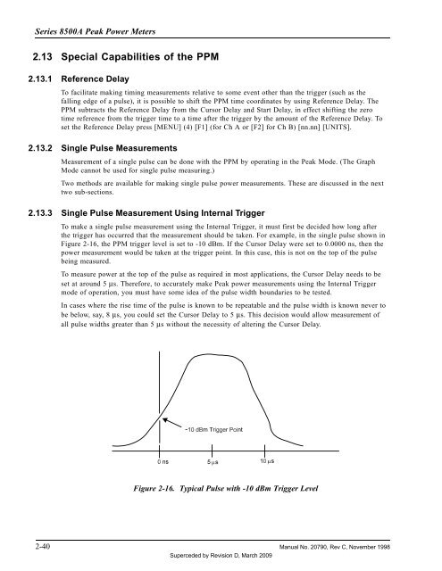
To make a single pulse measurement using the Internal Trigger, it must first be decided how long after<br />
the trigger has occurred that the measurement should be taken. For example, in the single pulse shown in<br />
Figure 2-16, the PPM trigger level is set to -10 dBm. If the Cursor Delay were set to 0.0000 ns, then the<br />
power measurement would be taken at the trigger point. In this case, this is not on the top of the pulse<br />
being measured.<br />
To measure power at the top of the pulse as required in most applications, the Cursor Delay needs to be<br />
set at around 5 µs. Therefore, to accurately make <strong>Peak</strong> power measurements using the Internal Trigger<br />
mode of operation, you must have some idea of the pulse width boundaries to be tested.<br />
In cases where the rise time of the pulse is known to be repeatable and the pulse width is known never to<br />
be below, say, 8 µs, you could set the Cursor Delay to 5 µs. This decision would allow measurement of<br />
all pulse widths greater than 5 µs without the necessity of altering the Cursor Delay.<br />
Figure 2-16. Typical Pulse with -10 dBm Trigger Level<br />
2-40 <strong>Manual</strong> No. 20790, Rev C, November 1998<br />
Superceded by Revision D, March 2009


