

Manual - 8500A Series Peak Power Meter - Giga-tronics
Manual - 8500A Series Peak Power Meter - Giga-tronics
Manual - 8500A Series Peak Power Meter - Giga-tronics

You also want an ePaper? Increase the reach of your titles
YUMPU automatically turns print PDFs into web optimized ePapers that Google loves.
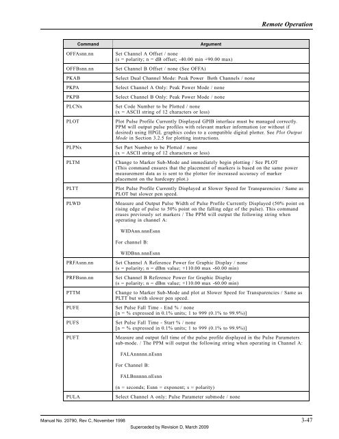
Remote Operation<br />
Command<br />
OFFAsnn.nn<br />
OFFBsnn.nn<br />
PKAB<br />
PKPA<br />
PKPB<br />
PLCNx<br />
PLOT<br />
PLPNx<br />
PLTM<br />
PLTT<br />
PLWD<br />
Argument<br />
Set Channel A Offset / none<br />
(s = polarity; n = dB offset; -40.00 min +90.00 max)<br />
Set Channel B Offset / none (See OFFA)<br />
Select Dual Channel Mode: <strong>Peak</strong> <strong>Power</strong> Both Channels / none<br />
Select Channel A Only: <strong>Peak</strong> <strong>Power</strong> Mode / none<br />
Select Channel B Only: <strong>Peak</strong> <strong>Power</strong> Mode / none<br />
Set Code Number to be Plotted / none<br />
(x = ASCII string of 12 characters or less)<br />
Plot Pulse Profile Currently Displayed GPIB interface must be managed correctly.<br />
PPM will output pulse profiles with relevant marker information (or without if<br />
desired) using HPGL graphics codes to a compatible digital plotter. See Plot Output<br />
Mode in Section 3.2.5 for plotting instructions.<br />
Set Part Number to be Plotted / none<br />
(x = ASCII string of 12 characters or less)<br />
Change to Marker Sub-Mode and immediately begin plotting / See PLOT<br />
(This command ensures that the placement of markers is based on the same power<br />
measurement data as is sent to the plotter for increased accuracy of marker<br />
placement on the hardcopy plot.)<br />
Plot Pulse Profile Currently Displayed at Slower Speed for Transparencies / Same as<br />
PLOT but slower pen speed.<br />
Measure and Output Pulse Width of Pulse Profile Currently Displayed (50% point on<br />
rising edge of pulse to 50% point on the falling edge of the pulse). This command<br />
erases previously set markers / The PPM will output the following string when<br />
operating in channel A:<br />
WIDAnn.nnnEsnn<br />
For channel B:<br />
WIDBnn.nnnEsnn<br />
PRFAsnn.nn<br />
PRFBsnn.nn<br />
PTTM<br />
PUFE<br />
PUFS<br />
PUFT<br />
Set Channel A Reference <strong>Power</strong> for Graphic Display / none<br />
(s = polarity; n = dBm value; +110.00 max -60.00 min)<br />
Set Channel B Reference <strong>Power</strong> for Graphic Display<br />
(s = polarity; n = dBm value; +110.00 max -60.00 min)<br />
Change to Marker Sub-Mode and plot at Slower Speed for Transparencies / Same as<br />
PLTT but with slower pen speed.<br />
Set Pulse Fall Time - End % / none<br />
[n = % expressed in 0.1% units; 1 to 999 (0.1% to 99.9%)]<br />
Set Pulse Fall Time - Start % / none<br />
[n = % expressed in 0.1% units; 1 to 999 (0.1% to 99.9%)]<br />
Measure and output fall time of the pulse profile displayed in the Pulse Parameters<br />
sub-mode. / The PPM will output the following string when operating in Channel A:<br />
FALAnnnnn.nEsnn<br />
For Channel B:<br />
FALBnnnnn.nEsnn<br />
(n = seconds; Esnn = exponent; s = polarity)<br />
PULA<br />
Select Channel A only: Pulse Parameter submode / none<br />
<strong>Manual</strong> No. 20790, Rev C, November 1998 3-47<br />
Superceded by Revision D, March 2009


