

Manual - 8500A Series Peak Power Meter - Giga-tronics
Manual - 8500A Series Peak Power Meter - Giga-tronics
Manual - 8500A Series Peak Power Meter - Giga-tronics

You also want an ePaper? Increase the reach of your titles
YUMPU automatically turns print PDFs into web optimized ePapers that Google loves.
Operation<br />
2.10.5 <strong>Power</strong> Ratio Measurements<br />
To make ratio measurements, the power measured by both channels must be within the specified power<br />
measurement range of the PPM system. When operating in CW, this power range is -40 to +20 dBm. In<br />
the <strong>Peak</strong> Mode, this power range is -20 to +20 dBm. <strong>Power</strong> readings taken in the Ratio Mode outside of<br />
these ranges will result in an error display.<br />
The Ratio Mode only provides the ratio of A/B, not vice versa. The PPM can ratio two CW signals, two<br />
<strong>Peak</strong> signals, or a combination of both. The following procedures show how to perform each of these<br />
ratio’ing operations.<br />
Ratio’ing Two CW Signals<br />
This is the easiest ratio function of the PPM. Proceed as follows:<br />
1. Allow the PPM to warm up for at least 30 minutes. Then Self-Calibrate both channels. From<br />
power-on, press [CW] [MENU] (1) [F3] [F1].<br />
Follow the displayed prompts to complete the Self-Cal. After Self-Cal has completed, the PPM<br />
will be measuring CW power in channel A.<br />
2. Select the Ratio Display Mode by pressing [MENU] (7) [F2].<br />
3. The default mode for power ratio measurements is for <strong>Peak</strong> power on both channels. To set both<br />
channels for CW operation, press [A] [F2] [B] [F2].<br />
The PPM will now be reading the ratio of A/B. Normally this is expressed in dB, however, it can also be<br />
expressed as a linear reading (such as 19654 EXP=-4) by pressing [dB/mW]. The display indicates that<br />
two CW signals are being ratio’ed by displaying CW/CW in the lower right hand corner of the display.<br />
Remember that the frequency of operation or Cal Factor must be entered using the FREQ key, and any<br />
desired Offsets should also be included. These two functions are described in Sections 2.8.3 and 2.8.4.<br />
Ratio’ing Two <strong>Peak</strong> Signals<br />
The point in time at which readings of <strong>Peak</strong> power are taken in both channels for ratio’ing purposes is<br />
determined by the setting of the Cursor Delay. Although it is most desirable that both pulses being<br />
monitored occur at exactly the same time, in practice this would be a very rare event. Therefore, the<br />
signals to be measured must be carefully evaluated to ensure that accurate readings are taken.<br />
The Cursor Delay must be set so that samples are being taken on both the channel A and B pulses. See<br />
Figures 2-12 and 2-13 for an examples of good and bad Cursor Delay settings in this situation.<br />
The following are guidelines that can be used when ratio’ing two <strong>Peak</strong> signals:<br />
1. Make a single channel <strong>Peak</strong> measurement using the Graph Mode (Autoscaling is recommended).<br />
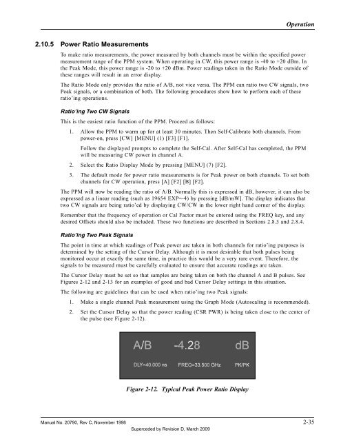
2. Set the Cursor Delay so that the power reading (CSR PWR) is being taken close to the center of<br />
the pulse (see Figure 2-12).<br />
Figure 2-12. Typical <strong>Peak</strong> <strong>Power</strong> Ratio Display<br />
<strong>Manual</strong> No. 20790, Rev C, November 1998 2-35<br />
Superceded by Revision D, March 2009


