

Manual - 8500A Series Peak Power Meter - Giga-tronics
Manual - 8500A Series Peak Power Meter - Giga-tronics
Manual - 8500A Series Peak Power Meter - Giga-tronics

You also want an ePaper? Increase the reach of your titles
YUMPU automatically turns print PDFs into web optimized ePapers that Google loves.
Operation<br />
4. To change the Cursor Delay for channel B, press the up or down arrow key. The spin knob can<br />
then be used to alter the channel B Cursor Delay. To lock out the spin knob and keyboard, press<br />
any UNITS key. To reactivate the spin knob and keyboard, press the up or down arrow key.<br />
5. If there are any difficulties due to timing factors, it is recommended that External Triggering be<br />
used. The trigger signal should occur slightly before the RF pulses to be measured. The Cursor<br />
Delays can then be used to place the Cursors on the pulses to allow readings to be taken.<br />
2.10.3 <strong>Peak</strong>, <strong>Peak</strong> Measurements: Method 2<br />
This method utilizes the Graph Mode to facilitate placing Cursors on the pulses of interest. Signal timing<br />
should be considered first of all. For purposes of discussion, assume the timing of the signals to be<br />
measured are similar to those shown in Figure 2-11.<br />
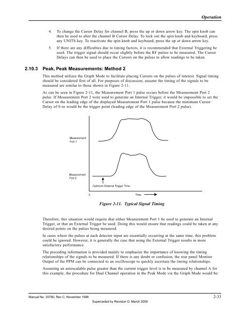
As can be seen in Figure 2-11, the Measurement Port 1 pulse occurs before the Measurement Port 2<br />
pulse. If Measurement Port 2 were used to generate an Internal Trigger, it would be impossible to set the<br />
Cursor on the leading edge of the displayed Measurement Port 1 pulse because the minimum Cursor<br />
Delay of 0 ns would be the trigger point (leading edge of the Measurement Port 2 pulse).<br />
Figure 2-11. Typical Signal Timing<br />
Therefore, this situation would require that either Measurement Port 1 be used to generate an Internal<br />
Trigger, or that an External Trigger be used. Doing this would ensure that readings could be taken at any<br />
desired points on the pulses being measured.<br />
In cases where the pulses at each detector input are essentially occurring at the same time, this problem<br />
could be ignored. However, it is generally the case that using the External Trigger results in more<br />
satisfactory performance.<br />
The preceding information is provided mainly to emphasize the importance of knowing the timing<br />
relationships of the signals to be measured. If there is any doubt or confusion, the rear panel Monitor<br />
Output of the PPM can be connected to an oscilloscope to quickly ascertain the timing relationships.<br />
Assuming an autoscalable pulse greater than the current trigger level is to be measured by channel A for<br />
this example, the procedure for Dual Channel operation in the <strong>Peak</strong> Mode via the Graph Mode would be:<br />
<strong>Manual</strong> No. 20790, Rev C, November 1998 2-33<br />
Superceded by Revision D, March 2009


