

Manual - 8500A Series Peak Power Meter - Giga-tronics
Manual - 8500A Series Peak Power Meter - Giga-tronics
Manual - 8500A Series Peak Power Meter - Giga-tronics

You also want an ePaper? Increase the reach of your titles
YUMPU automatically turns print PDFs into web optimized ePapers that Google loves.
<strong>Series</strong> <strong>8500A</strong> <strong>Peak</strong> <strong>Power</strong> <strong>Meter</strong>s<br />
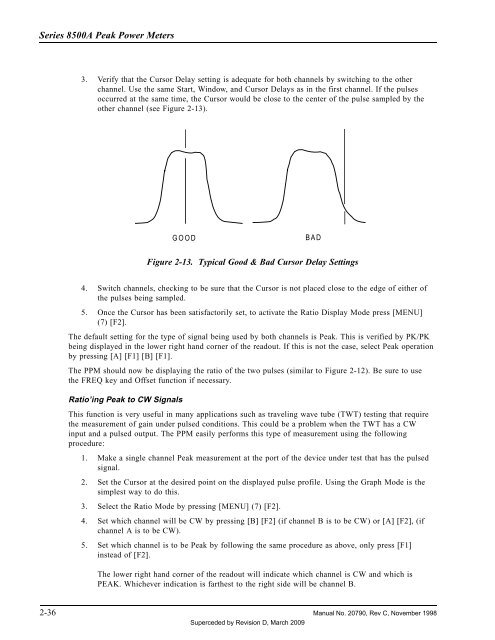
3. Verify that the Cursor Delay setting is adequate for both channels by switching to the other<br />
channel. Use the same Start, Window, and Cursor Delays as in the first channel. If the pulses<br />
occurred at the same time, the Cursor would be close to the center of the pulse sampled by the<br />
other channel (see Figure 2-13).<br />
GOOD<br />
BAD<br />
Figure 2-13. Typical Good & Bad Cursor Delay Settings<br />
4. Switch channels, checking to be sure that the Cursor is not placed close to the edge of either of<br />
the pulses being sampled.<br />
5. Once the Cursor has been satisfactorily set, to activate the Ratio Display Mode press [MENU]<br />
(7) [F2].<br />
The default setting for the type of signal being used by both channels is <strong>Peak</strong>. This is verified by PK/PK<br />
being displayed in the lower right hand corner of the readout. If this is not the case, select <strong>Peak</strong> operation<br />
by pressing [A] [F1] [B] [F1].<br />
The PPM should now be displaying the ratio of the two pulses (similar to Figure 2-12). Be sure to use<br />
the FREQ key and Offset function if necessary.<br />
Ratio’ing <strong>Peak</strong> to CW Signals<br />
This function is very useful in many applications such as traveling wave tube (TWT) testing that require<br />
the measurement of gain under pulsed conditions. This could be a problem when the TWT has a CW<br />
input and a pulsed output. The PPM easily performs this type of measurement using the following<br />
procedure:<br />
1. Make a single channel <strong>Peak</strong> measurement at the port of the device under test that has the pulsed<br />
signal.<br />
2. Set the Cursor at the desired point on the displayed pulse profile. Using the Graph Mode is the<br />
simplest way to do this.<br />
3. Select the Ratio Mode by pressing [MENU] (7) [F2].<br />
4. Set which channel will be CW by pressing [B] [F2] (if channel B is to be CW) or [A] [F2], (if<br />
channel A is to be CW).<br />
5. Set which channel is to be <strong>Peak</strong> by following the same procedure as above, only press [F1]<br />
instead of [F2].<br />
The lower right hand corner of the readout will indicate which channel is CW and which is<br />
PEAK. Whichever indication is farthest to the right side will be channel B.<br />
2-36 <strong>Manual</strong> No. 20790, Rev C, November 1998<br />
Superceded by Revision D, March 2009


