

Manual - 8500A Series Peak Power Meter - Giga-tronics
Manual - 8500A Series Peak Power Meter - Giga-tronics
Manual - 8500A Series Peak Power Meter - Giga-tronics

Create successful ePaper yourself
Turn your PDF publications into a flip-book with our unique Google optimized e-Paper software.
<strong>Series</strong> <strong>8500A</strong> <strong>Peak</strong> <strong>Power</strong> <strong>Meter</strong>s<br />
Command<br />
Argument<br />
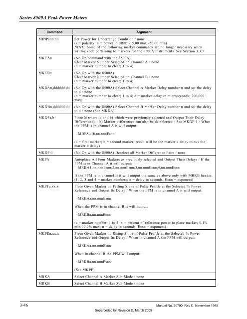
MINPsnn.nn<br />
Set <strong>Power</strong> for Underrange Condition / none<br />
(s = polarity; n = power in dBm; -15.00 max -50.00 min)<br />
NOTE: Some of the following marker commands are no longer necessary when<br />
writing code pertaining to markers for the <strong>8500A</strong> instruments. See Section 3.3.7<br />
MKCAn (No Op command with the <strong>8500A</strong>)<br />
Clear Marker Number Selected on Channel A / none<br />
(n = marker number to clear; 1 to 4)<br />
MKCBn (No Op with the <strong>8500A</strong>)<br />
Clear Marker Number Selected on Channel B / none<br />
(n = marker number to clear; 1 to 4)<br />
MKDAn,dddddd.dd<br />
MKDBn,dddddd.dd<br />
MKDFa,b<br />
(No Op with the <strong>8500A</strong>) Select Channel A Marker Delay number n and set the delay<br />
to d / none<br />
(n = marker number to clear; 1 to 4; d = marker delay in microseconds; 200,000<br />
max)<br />
(No Op with the <strong>8500A</strong>) Select Channel B Marker Delay number n and set the delay<br />
to d / none (See MKDA)<br />
Place Markers (a and b) which were previously selected and Output Their Delay<br />
Difference (a - b) Marker differences can also be de-selected - See MKDF-1 / When<br />
the PPM is in channel A it will output:<br />
MDFA,a-b,nn.nnnEsnn<br />
(a = first marker; b = second marker; result will be the marker a delay minus the<br />
marker b delay)<br />
MKDF-1<br />
MKPA<br />
(No Op with the <strong>8500A</strong>) Deselect all Marker Difference Pairs / none<br />
Autoplace All Four Markers as previously selected and Output Their Delays / If the<br />
PPM is in Channel A it will output:<br />
MRKA1,nn.nnnEsnn;2,nn.nnnEsnn;3,nn.nnnEsnn;4,nn.nnnEsnn<br />
If the PPM is in channel B it will output the same as above only with MRKB header.<br />
(1, 2, 3 and 4 = marker numbers; n = delay in seconds; Esnn = exponent)<br />
MKPFa,xx.x<br />
Place Given Marker on Falling Slope of Pulse Profile at the Selected % <strong>Power</strong><br />
Reference and Output Its Delay / When the PPM is in channel A it will output:<br />
MRKAa,nn.nnnEsnn<br />
When the PPM is in channel B it will output:<br />
MRKBa,nn.nnnEsnn<br />
(a = marker number; 1 to 4; x = percent of reference power to place marker; 0.1%<br />
min 99.9% max; n = delay in seconds; Esnn = exponent)<br />
MKPRa,xx.x<br />
Place Given Marker on Rising Slope of Pulse Profile at the Selected % <strong>Power</strong><br />
Reference and Output Its Delay / When in channel A the PPM will output:<br />
MRKAa,nn.nnnEsnn<br />
When in channel B the PPM will output:<br />
MRKBa,nn.nnnEsnn<br />
(See MKPF)<br />
MRKA<br />
MRKB<br />
Select Channel A Marker Sub-Mode / none<br />
Select Channel B Marker Sub-Mode / none<br />
3-46 <strong>Manual</strong> No. 20790, Rev C, November 1998<br />
Superceded by Revision D, March 2009


