

Manual - 8500A Series Peak Power Meter - Giga-tronics
Manual - 8500A Series Peak Power Meter - Giga-tronics
Manual - 8500A Series Peak Power Meter - Giga-tronics

Create successful ePaper yourself
Turn your PDF publications into a flip-book with our unique Google optimized e-Paper software.
<strong>Series</strong> <strong>8500A</strong> <strong>Peak</strong> <strong>Power</strong> <strong>Meter</strong>s<br />
5.3.1 Calibration Equipment Required<br />
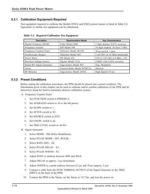
Test equipment required to calibrate the Models 8501A and 8502A power meters is listed in Table 5-2.<br />
Equivalent or similar test equipment can be substituted.<br />
Table 5-2. Required Calibration Test Equipment<br />
Description Representative Model Key Characteristics<br />
Digital Voltmeter (DVM) Fluke Model 8800 5 digit display, 0.01% accuracy<br />
Frequency Counter EIP Model 548 10 digit readout. At least 1 GHz<br />
Frequency Counter/Timer Tektronix Model DC509 30 µs period, 1 ppm<br />
Oscilloscope (Scope) Tektronix Model 465 5 mV/DIV & 50 MHz bandwidth<br />
<strong>Power</strong> <strong>Meter</strong> HP Model 432 0.95 to 1.05 GHz at 0 dBm, 1.3%<br />
Precision Voltage Source Digitec Model 3110 5.000V with 0.02% accuracy<br />
Pulsed RF Signal Generator <strong>Giga</strong>-<strong>tronics</strong> Model 907 Trig. Modulator<br />
Variac General Radio Model W5MT3A <strong>Meter</strong>ed<br />
RF Detector <strong>Giga</strong>-<strong>tronics</strong> Model 16936 High Speed (15 ns)<br />
5.3.2 Preset Conditions<br />
Before stating the calibration procedures, the PPM should be placed into a preset condition. The<br />
Information given in this chapter can be used to calibrate and/or confirm calibration of the PPM and its<br />
detector(s) using the built-in automatic detector calibration system.<br />
A. Frequency Counter/Timer<br />
1. Set FUNCTION switch to PERIOD A.<br />
2. Set AVERAGES switch to 10 to the 6th power.<br />
3. Set SLOPE switch to +.<br />
4. Set ATTEN switch to X1.<br />
5. Set SOURCE switch to EXT.<br />
6. Set COUPL switch to dc.<br />
7. Set TRIG LEVEL switch to AUTO.<br />
B. Signal Generator<br />
1. Select MODE - PM (Pulse Modulation).<br />
2. Select PULSE MODE - INT -PULSE.<br />
3. Select RATE (HZ) - 1K.<br />
4. Select PULSE DELAY - X1.<br />
5. Select PULSE WIDTH - X1.<br />
6. Adjust RATE to midway between MIN and MAX.<br />
7. Adjust DELAY to approx. 3 µs (minimum).<br />
8. Adjust WIDTH to a point midway between 0.2 µs and 10 µs (approx. 5 µs).<br />
9. Connect a cable from the SYNC NORMAL OUTPUT of the Signal Generator to the TRIG<br />
INPUT on the back of the PPM.<br />
10. Connect the PPM to the Variac, set the Variac to 115 Vac, and turn the power on.<br />
5-10 <strong>Manual</strong> No. 20790, Rev C, November 1998<br />
Superceded by Revision D, March 2009


