Xilinx Constraints Guide
Xilinx Constraints Guide
Xilinx Constraints Guide
You also want an ePaper? Increase the reach of your titles
YUMPU automatically turns print PDFs into web optimized ePapers that Google loves.
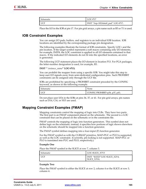
Schematic LOC=P17<br />
Chapter 4: <strong>Xilinx</strong> <strong>Constraints</strong><br />
UCF INST “/top-102/data0_pad” LOC=P17;<br />
Place the I/O in the IOB at pin 17. For pin grid arrays, a pin name such as B3 or T1 is used.<br />
IOB Constraint Examples<br />
You can assign I/O pads, buffers, and registers to an individual IOB location. IOB<br />
locations are identified by the corresponding package pin designation.<br />
The following examples illustrate the format of IOB constraints. Specify LOC= and the<br />
pin location. If the target symbol represents a soft macro containing only I/O elements,<br />
for example, INFF8, the LOC constraint is applied to all I/O elements contained in that<br />
macro. If the indicated I/O elements do not fit into the specified locations, an error<br />
is generated.<br />
The following UCF statement places the I/O element in location P13. For PGA packages,<br />
the letter-number designation is used, for example, B3.<br />
INST “ instance_name” LOC=P13;<br />
You can prohibit the mapper from using a specific IOB. You might take this step to<br />
keep user I/O signals away from semi-dedicated configuration pins. Such PROHIBIT<br />
constraints can be assigned only through the UCF file.<br />
IOBs are prohibited by specifying a PROHIBIT constraint preceded by the CONFIG<br />
keyword, as shown in the following example.<br />
Schematic None<br />
UCF CONFIG PROHIBIT=p36, p37, p41;<br />
Do not place user I/Os in the IOBs at pins 36, 37, or 41. For pin grid arrays, pin names<br />
such as D14, C16, or H15 are used.<br />
Mapping Constraint Examples (FMAP)<br />
Mapping constraints control the mapping of logic into CLBs. They have two parts.<br />
The first part is an FMAP component placed on the schematic. The second is a LOC<br />
constraint that can be placed on the schematic or in the constraints file.<br />
FMAP controls the mapping of logic into function generators. This symbol does not<br />
define logic on the schematic; instead, it specifies how portions of logic shown elsewhere<br />
on the schematic should be mapped into a function generator.<br />
The FMAP symbol defines mapping into a four-input (F) function generator.<br />
For the FMAP symbol as with the CLBMAP primitive, MAP=PUC or PUO is supported,<br />
as well as the LOC constraint. (Currently, pin locking is not supported. MAP=PLC or<br />
PLO is translated into PUC and PUO, respectively.)<br />
Example One<br />
Place the FMAP symbol in the SLICE at row 7, column 3.<br />
Schematic LOC=SLICE_X7Y3<br />
UCF INST “$1I323”LOC=SLICE_X2Y4,<br />
SLICE_X3Y4;<br />
Example Two<br />
Place the FMAP symbol in either the SLICE at row 2, column 4 or the SLICE at row 3,<br />
column 4.<br />
<strong>Constraints</strong> <strong>Guide</strong><br />
UG625 (v. 13.2) July 6, 2011 www.xilinx.com 165


