Xilinx Constraints Guide
Xilinx Constraints Guide
Xilinx Constraints Guide

You also want an ePaper? Increase the reach of your titles
YUMPU automatically turns print PDFs into web optimized ePapers that Google loves.
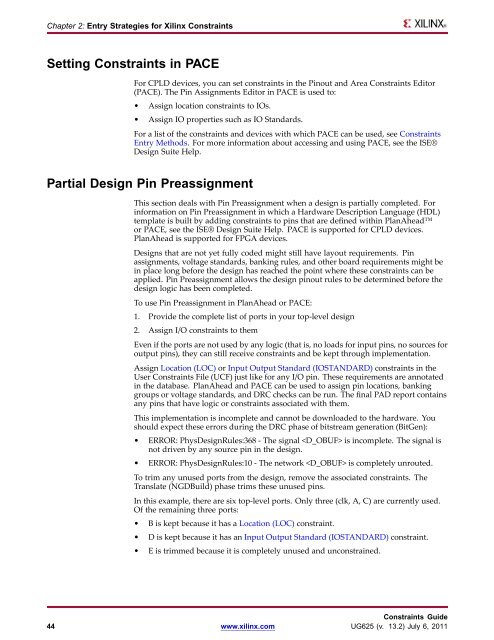
Chapter 2: Entry Strategies for <strong>Xilinx</strong> <strong>Constraints</strong><br />
Setting <strong>Constraints</strong> in PACE<br />
For CPLD devices, you can set constraints in the Pinout and Area <strong>Constraints</strong> Editor<br />
(PACE). The Pin Assignments Editor in PACE is used to:<br />
• Assign location constraints to IOs.<br />
• Assign IO properties such as IO Standards.<br />
For a list of the constraints and devices with which PACE can be used, see <strong>Constraints</strong><br />
Entry Methods. For more information about accessing and using PACE, see the ISE®<br />
Design Suite Help.<br />
Partial Design Pin Preassignment<br />
This section deals with Pin Preassignment when a design is partially completed. For<br />
information on Pin Preassignment in which a Hardware Description Language (HDL)<br />
template is built by adding constraints to pins that are defined within PlanAhead<br />
or PACE, see the ISE® Design Suite Help. PACE is supported for CPLD devices.<br />
PlanAhead is supported for FPGA devices.<br />
Designs that are not yet fully coded might still have layout requirements. Pin<br />
assignments, voltage standards, banking rules, and other board requirements might be<br />
in place long before the design has reached the point where these constraints can be<br />
applied. Pin Preassignment allows the design pinout rules to be determined before the<br />
design logic has been completed.<br />
To use Pin Preassignment in PlanAhead or PACE:<br />
1. Provide the complete list of ports in your top-level design<br />
2. Assign I/O constraints to them<br />
Even if the ports are not used by any logic (that is, no loads for input pins, no sources for<br />
output pins), they can still receive constraints and be kept through implementation.<br />
Assign Location (LOC) or Input Output Standard (IOSTANDARD) constraints in the<br />
User <strong>Constraints</strong> File (UCF) just like for any I/O pin. These requirements are annotated<br />
in the database. PlanAhead and PACE can be used to assign pin locations, banking<br />
groups or voltage standards, and DRC checks can be run. The final PAD report contains<br />
any pins that have logic or constraints associated with them.<br />
This implementation is incomplete and cannot be downloaded to the hardware. You<br />
should expect these errors during the DRC phase of bitstream generation (BitGen):<br />
• ERROR: PhysDesignRules:368 - The signal is incomplete. The signal is<br />
not driven by any source pin in the design.<br />
• ERROR: PhysDesignRules:10 - The network is completely unrouted.<br />
To trim any unused ports from the design, remove the associated constraints. The<br />
Translate (NGDBuild) phase trims these unused pins.<br />
In this example, there are six top-level ports. Only three (clk, A, C) are currently used.<br />
Of the remaining three ports:<br />
• B is kept because it has a Location (LOC) constraint.<br />
• D is kept because it has an Input Output Standard (IOSTANDARD) constraint.<br />
• E is trimmed because it is completely unused and unconstrained.<br />
<strong>Constraints</strong> <strong>Guide</strong><br />
44 www.xilinx.com UG625 (v. 13.2) July 6, 2011