

Chapter 10 Memory Subsystem.pdf
Chapter 10 Memory Subsystem.pdf
Chapter 10 Memory Subsystem.pdf

You also want an ePaper? Increase the reach of your titles
YUMPU automatically turns print PDFs into web optimized ePapers that Google loves.
Public Version<br />
General-Purpose <strong>Memory</strong> Controller www.ti.com<br />
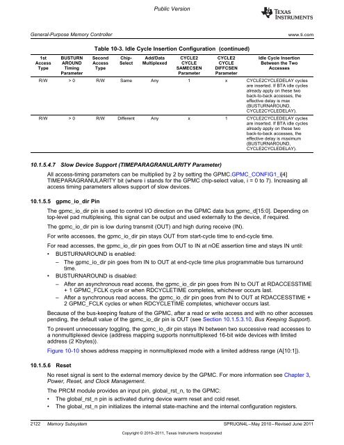
Table <strong>10</strong>-3. Idle Cycle Insertion Configuration (continued)<br />
1st BUSTURN Second Chip- Add/Data CYCLE2 CYCLE2 Idle Cycle Insertion<br />
Access AROUND Access Select Multiplexed CYCLE CYCLE Between the Two<br />
Type Timing Type SAMECSEN DIFFCSEN Accesses<br />
Parameter Parameter Parameter<br />
R/W > 0 R/W Same Any 1 x CYCLE2CYCLEDELAY cycles<br />
are inserted. If BTA idle cycles<br />
already apply on these two<br />
back-to-back accesses, the<br />
effective delay is max<br />
(BUSTURNAROUND,<br />
CYCLE2CYCLEDELAY).<br />
R/W > 0 R/W Different Any x 1 CYCLE2CYCLEDELAY cycles<br />
are inserted. If BTA idle cycles<br />
already apply on these two<br />
back-to-back accesses, the<br />
effective delay is maximum<br />
(BUSTURNAROUND,<br />
CYCLE2CYCLEDELAY).<br />
<strong>10</strong>.1.5.4.7 Slow Device Support (TIMEPARAGRANULARITY Parameter)<br />
All access-timing parameters can be multiplied by 2 by setting the GPMC.GPMC_CONFIG1_i[4]<br />
TIMEPARAGRANULARITY bit (where i stands for the GPMC chip-select value, i = 0 to 7). Increasing all<br />
access timing parameters allows support of slow devices.<br />
<strong>10</strong>.1.5.5 gpmc_io_dir Pin<br />
The gpmc_io_dir pin is used to control I/O direction on the GPMC data bus gpmc_d[15:0]. Depending on<br />
top-level pad multiplexing, this signal can be output and used externally to the device, if required.<br />
The gpmc_io_dir pin is low during transmit (OUT) and high during receive (IN).<br />
For write accesses, the gpmc_io_dir pin stays OUT from start-cycle time to end-cycle time.<br />
For read accesses, the gpmc_io_dir pin goes from OUT to IN at nOE assertion time and stays IN until:<br />
• BUSTURNAROUND is enabled:<br />
– The gpmc_io_dir pin goes from IN to OUT at end-cycle time plus programmable bus turnaround<br />
time.<br />
• BUSTURNAROUND is disabled:<br />
– After an asynchronous read access, the gpmc_io_dir pin goes from IN to OUT at RDACCESSTIME<br />
+ 1 GPMC_FCLK cycle or when RDCYCLETIME completes, whichever occurs last.<br />
– After a synchronous read access, the gpmc_io_dir pin goes from IN to OUT at RDACCESSTIME +<br />
2 GPMC_FCLK cycles or when RDCYCLETIME completes, whichever occurs last.<br />
Because of the bus-keeping feature of the GPMC, after a read or write access and with no other accesses<br />
pending, the default value of the gpmc_io_dir pin is OUT (see Section <strong>10</strong>.1.5.3.<strong>10</strong>, Bus Keeping Support).<br />
To prevent unnecessary toggling, the gpmc_io_dir pin stays IN between two successive read accesses to<br />
a nonmultiplexed device (address mapping supports nonmultiplexed 16-bit wide devices with limited<br />
address (2 Kbytes)).<br />
Figure <strong>10</strong>-<strong>10</strong> shows address mapping in nonmultiplexed mode with a limited address range (A[<strong>10</strong>:1]).<br />
<strong>10</strong>.1.5.6 Reset<br />
No reset signal is sent to the external memory device by the GPMC. For more information see <strong>Chapter</strong> 3,<br />
Power, Reset, and Clock Management.<br />
The PRCM module provides an input pin, global_rst_n, to the GPMC:<br />
• The global_rst_n pin is activated during device warm reset and cold reset.<br />
• The global_rst_n pin initializes the internal state-machine and the internal configuration registers.<br />
2122 <strong>Memory</strong> <strong>Subsystem</strong> SPRUGN4L–May 20<strong>10</strong>–Revised June 2011<br />
Copyright © 20<strong>10</strong>–2011, Texas Instruments Incorporated


