

Chapter 10 Memory Subsystem.pdf
Chapter 10 Memory Subsystem.pdf
Chapter 10 Memory Subsystem.pdf

You also want an ePaper? Increase the reach of your titles
YUMPU automatically turns print PDFs into web optimized ePapers that Google loves.
Public Version<br />
General-Purpose <strong>Memory</strong> Controller www.ti.com<br />
PFPWENROUNDROBIN bit. When a request to another chip-select is received while the prefetch and<br />
write-posting engine is active, priority is given to the new request. The request processed thereafter is the<br />
prefetch and write-posting engine request, even if another interconnect request is passed in the mean<br />
time. The engine keeps control of the bus for an additional number of requests programmed in the<br />
GPMC.GPMC_PREFETCH_CONFIG1[19:16] PFPWWEIGHTEDPRIO bit field. Control is then passed to<br />
the direct interconnect request.<br />
As an example, the round-robin arbitration scheme is selected with PFPWWEIGHTEDPRIO set to 0x2.<br />
Considering the prefetch and write-posting engine and the interconnect interface are always requesting<br />
access to the external interface, the GPMC grants priority to the direct interconnect access for one<br />
request. The GPMC then grants priority to the engine for three requests, and finnaly back to the direct<br />
interconnect access, until the arbiter is reset when one of the two initiators stops initiating requests.<br />
<strong>10</strong>.1.6 GPMC Use Cases and Tips<br />
<strong>10</strong>.1.6.1 How to Set GPMC Timing Parameters for Typical Accesses<br />
<strong>10</strong>.1.6.1.1 External <strong>Memory</strong> Attached to the GPMC Module<br />
As discussed in the introduction to this chapter, the GPMC module supports the following external<br />
memory types:<br />
• Asynchronous or synchronous, 8-bit or 16-bit-width memory or device<br />
• 16-bit address/data-multiplexed or not multiplexed NOR flash device<br />
• 8- or 16-bit NAND flash device<br />
The following examples show how to calculate GPMC timing parameters by showing a typical parameter<br />
setup for the access to be performed.<br />
The example is based on a 512-Mb multiplexed NOR flash memory with the following characteristics:<br />
• Type: NOR flash (address/data-multiplexed mode)<br />
• Size: 512M bits<br />
• Data Bus: 16 bits wide<br />
• Speed: <strong>10</strong>4-MHz clock frequency<br />
• Read access time: 80 ns<br />
<strong>10</strong>.1.6.1.2 Typical GPMC Setup<br />
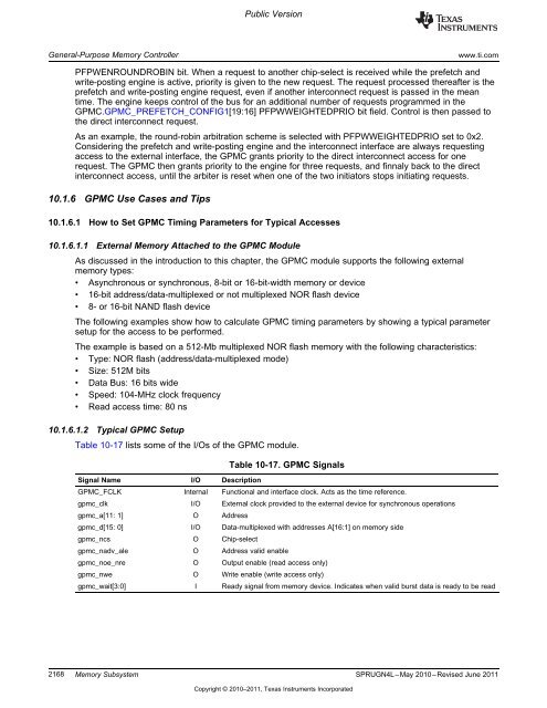
Table <strong>10</strong>-17 lists some of the I/Os of the GPMC module.<br />
Signal Name I/O Description<br />
Table <strong>10</strong>-17. GPMC Signals<br />
GPMC_FCLK Internal Functional and interface clock. Acts as the time reference.<br />
gpmc_clk I/O External clock provided to the external device for synchronous operations<br />
gpmc_a[11: 1] O Address<br />
gpmc_d[15: 0] I/O Data-multiplexed with addresses A[16:1] on memory side<br />
gpmc_ncs O Chip-select<br />
gpmc_nadv_ale O Address valid enable<br />
gpmc_noe_nre O Output enable (read access only)<br />
gpmc_nwe O Write enable (write access only)<br />
gpmc_wait[3:0] I Ready signal from memory device. Indicates when valid burst data is ready to be read<br />
2168 <strong>Memory</strong> <strong>Subsystem</strong> SPRUGN4L–May 20<strong>10</strong>–Revised June 2011<br />
Copyright © 20<strong>10</strong>–2011, Texas Instruments Incorporated


