NXS Form 63-2600, Users Manual, Technical Data - CONTROL ...
NXS Form 63-2600, Users Manual, Technical Data - CONTROL ...
NXS Form 63-2600, Users Manual, Technical Data - CONTROL ...
- No tags were found...

You also want an ePaper? Increase the reach of your titles
YUMPU automatically turns print PDFs into web optimized ePapers that Google loves.
108(110) Fault tracing<br />
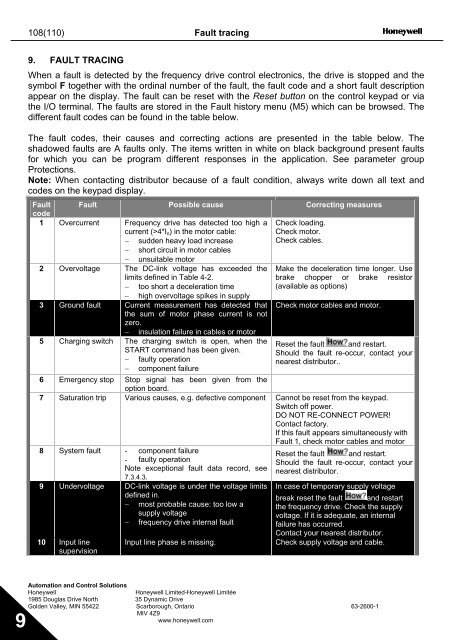
9. FAULT TRACING<br />
When a fault is detected by the frequency drive control electronics, the drive is stopped and the<br />
symbol F together with the ordinal number of the fault, the fault code and a short fault description<br />
appear on the display. The fault can be reset with the Reset button on the control keypad or via<br />
the I/O terminal. The faults are stored in the Fault history menu (M5) which can be browsed. The<br />
different fault codes can be found in the table below.<br />
The fault codes, their causes and correcting actions are presented in the table below. The<br />
shadowed faults are A faults only. The items written in white on black background present faults<br />
for which you can be program different responses in the application. See parameter group<br />
Protections.<br />
Note: When contacting distributor because of a fault condition, always write down all text and<br />
codes on the keypad display.<br />
Fault Fault Possible cause Correcting measures<br />
code<br />
1 Overcurrent Frequency drive has detected too high a<br />
current (>4*I n ) in the motor cable:<br />
Check loading.<br />
Check motor.<br />
− sudden heavy load increase<br />
Check cables.<br />
− short circuit in motor cables<br />
− unsuitable motor<br />
2 Overvoltage The DC-link voltage has exceeded the Make the deceleration time longer. Use<br />
limits defined in Table 4-2.<br />
brake chopper or brake resistor<br />
− too short a deceleration time<br />
(available as options)<br />
− high overvoltage spikes in supply<br />
3 Ground fault Current measurement has detected that Check motor cables and motor.<br />
the sum of motor phase current is not<br />
zero.<br />
− insulation failure in cables or motor<br />
5 Charging switch The charging switch is open, when the Reset the fault and restart.<br />
START command has been given. Should the fault re-occur, contact your<br />
− faulty operation<br />
nearest distributor..<br />
− component failure<br />
6 Emergency stop Stop signal has been given from the<br />
option board.<br />
7 Saturation trip Various causes, e.g. defective component Cannot be reset from the keypad.<br />
Switch off power.<br />
DO NOT RE-CONNECT POWER!<br />
Contact factory.<br />
If this fault appears simultaneously with<br />
Fault 1, check motor cables and motor<br />
8 System fault - component failure<br />
- faulty operation<br />
Note exceptional fault data record, see<br />
7.3.4.3.<br />
9 Undervoltage DC-link voltage is under the voltage limits<br />
defined in.<br />
− most probable cause: too low a<br />
supply voltage<br />
− frequency drive internal fault<br />
10 Input line<br />
supervision<br />
Input line phase is missing.<br />
Reset the fault and restart.<br />
Should the fault re-occur, contact your<br />
nearest distributor.<br />
In case of temporary supply voltage<br />
break reset the fault and restart<br />
the frequency drive. Check the supply<br />
voltage. If it is adequate, an internal<br />
failure has occurred.<br />
Contact your nearest distributor.<br />
Check supply voltage and cable.<br />
Automation and Control Solutions<br />
Honeywell<br />
Honeywell Limited-Honeywell Limitée<br />
1985 Douglas Drive North 35 Dynamic Drive<br />
Golden Valley, MIN 55422 Scarborough, Ontario <strong>63</strong>-<strong>2600</strong>-1<br />
MIV 4Z9<br />
www.honeywell.com<br />
9