NXS Form 63-2600, Users Manual, Technical Data - CONTROL ...
NXS Form 63-2600, Users Manual, Technical Data - CONTROL ...
NXS Form 63-2600, Users Manual, Technical Data - CONTROL ...
- No tags were found...

Create successful ePaper yourself
Turn your PDF publications into a flip-book with our unique Google optimized e-Paper software.
Cabling and connections 65(110)<br />
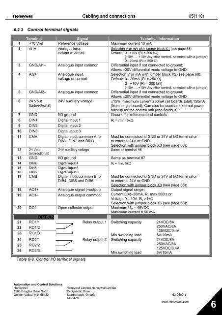
6.2.3 Control terminal signals<br />
Terminal Signal <strong>Technical</strong> information<br />
1 +10 Vref Reference voltage Maximum current 10 mA<br />
2 AI1+ Analogue input,<br />
voltage or current<br />
Selection V or mA with jumper block X1 (see page 68):<br />
Default: 0– +10V (Ri = 200 kΩ)<br />
(-10V…..+10V Joy-stick control, selected with a jumper)<br />
0– 20mA (Ri = 250 Ω)<br />
3 GND/AI1– Analogue input common Differential input if not connected to ground;<br />
Allows ±20V differential mode voltage to GND<br />
4 AI2+ Analogue input,<br />
voltage or current<br />
Selection V or mA with jumper block X2 (see page 68):<br />
Default: 0– 20mA (Ri = 250 Ω)<br />
0– +10V (Ri = 200 kΩ)<br />
(-10V…..+10V Joy-stick control, selected with a jumper)<br />
5 GND/AI2– Analogue input common Differential input if not connected to ground;<br />
Allows ±20V differential mode voltage to GND<br />
6 24 Vout<br />
(bidirectional)<br />
24V auxiliary voltage<br />
±15%, maximum current 250mA (all boards total);150mA<br />
(from single board); Can also be used as external power<br />
backup for the control unit (and fieldbus)<br />
7 GND I/O ground Ground for reference and controls<br />
8 DIN1 Digital input 1<br />
R i = min. 5kΩ<br />
9 DIN2 Digital input 2<br />
10 DIN3 Digital input 3<br />
11 CMA Digital input common A for<br />
DIN1, DIN2 and DIN3.<br />
Must be connected to GND or 24V of I/O terminal or<br />
to external 24V or GND<br />
Selection with jumper block X3 (see page 68):<br />
12 24 Vout<br />
24V auxiliary voltage Same as terminal #6<br />
(bidirectional)<br />
13 GND I/O ground Same as terminal #7<br />
14 DIN4 Digital input 4<br />
R i = min. 5kΩ<br />
15 DIN5 Digital input 5<br />
16 DIN6 Digital input 6<br />
17 CMB Digital input common B for<br />
DIB4, DIB5 and DIB6<br />
Must be connected to GND or 24V of I/O terminal or<br />
to external 24V or GND<br />
18 AO1+ Analogue signal (+output)<br />
19 AO1– Analogue output common<br />
Selection with jumper block X3 (see page 68):<br />
Output signal range:<br />
Current 0(4)–20mA, R L max 500Ω or<br />
Voltage 0—10V, R L >1kΩ<br />
Selection with jumper block X6 (see page 68):<br />
20 DO1 Open collector output Maximum U in = 48VDC<br />
Maximum current = 50 mA<br />
OPT-A2<br />
21 RO1/1<br />
22 RO1/2<br />
23 RO1/3<br />
24 RO2/1<br />
25 RO2/2<br />
26 RO2/3<br />
Table 6-9. Control I/O terminal signals<br />
Relay output 1 Switching capacity 24VDC/8A<br />
250VAC/8A<br />
125VDC/0.4A<br />
Min.switching load 5V/10mA<br />
Relay output 2 Switching capacity 24VDC/8A<br />
250VAC/8A<br />
125VDC/0.4A<br />
Min.switching load 5V/10mA<br />
Automation and Control Solutions<br />
Honeywell<br />
Honeywell Limited-Honeywell Limitée<br />
1985 Douglas Drive North 35 Dynamic Drive<br />
Golden Valley, MIN 55422 Scarborough, Ontario <strong>63</strong>-<strong>2600</strong>-1<br />
MIV 4Z9<br />
www.honeywell.com<br />
6