NXS Form 63-2600, Users Manual, Technical Data - CONTROL ...
NXS Form 63-2600, Users Manual, Technical Data - CONTROL ...
NXS Form 63-2600, Users Manual, Technical Data - CONTROL ...
- No tags were found...

You also want an ePaper? Increase the reach of your titles
YUMPU automatically turns print PDFs into web optimized ePapers that Google loves.
Honeywell Multi-purpose Control Application 69<br />
6.6 Multi-purpose Control Application – Parameter lists<br />
On the next pages you will find the lists of parameters within the respective parameter groups. The<br />
parameter descriptions are given on pages 122 to 209.<br />
Column explanations:<br />
Code = Location indication on the keypad; Shows the operator the present parameter number<br />
Parameter = Name of parameter<br />
Min = Minimum value of parameter<br />
Max = Maximum value of parameter<br />
Unit = Unit of parameter value; Given if available<br />
Default = Value preset by factory<br />
Cust = Customer’s own setting<br />
ID = ID number of the parameter<br />
= On param. code: Parameter value can only be changed after the FC has been<br />
stopped<br />
= Apply the Terminal to Function method (TTF) to these parameters (see chapter 6.4)<br />
= Monitoring values controllable from fieldbus using the ID number<br />
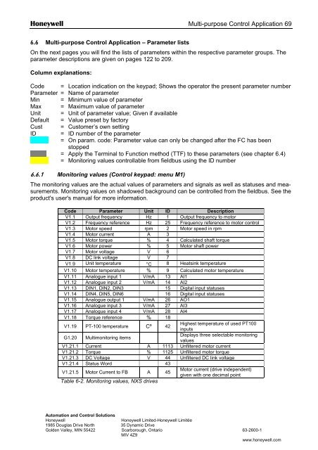
6.6.1 Monitoring values (Control keypad: menu M1)<br />
The monitoring values are the actual values of parameters and signals as well as statuses and measurements.<br />
Monitoring values on shadowed background can be controlled from the fieldbus. See the<br />
product's user's manual for more information.<br />
Code Parameter Unit ID Description<br />
V1.1 Output frequency Hz 1 Output frequency to motor<br />
V1.2 Frequency reference Hz 25 Frequency reference to motor control<br />
V1.3 Motor speed rpm 2 Motor speed in rpm<br />
V1.4 Motor current A 3<br />
V1.5 Motor torque % 4 Calculated shaft torque<br />
V1.6 Motor power % 5 Motor shaft power<br />
V1.7 Motor voltage V 6<br />
V1.8 DC link voltage V 7<br />
V1.9 Unit temperature °C 8 Heatsink temperature<br />
V1.10 Motor temperature % 9 Calculated motor temperature<br />
V1.11 Analogue input 1 V/mA 13 AI1<br />
V1.12 Analogue input 2 V/mA 14 AI2<br />
V1.13 DIN1, DIN2, DIN3 15 Digital input statuses<br />
V1.14 DIN4, DIN5, DIN6 16 Digital input statuses<br />
V1.15 Analogue output 1 V/mA 26 AO1<br />
V1.16 Analogue input 3 V/mA 27 AI3<br />
V1.17 Analogue input 4 V/mA 28 AI4<br />
V1.18 Torque reference % 18<br />
V1.19 PT-100 temperature Cº 42<br />
Highest temperature of used PT100<br />
G1.20 Multimonitoring items<br />
inputs<br />
Displays three selectable monitoring<br />
values<br />
V1.21.1 Current A 1113 Unfiltered motor current<br />
V1.21.2 Torque % 1125 Unfiltered motor torque<br />
V1.21.3 DC Voltage V 44 Unfiltered DC link voltage<br />
V1.21.4 Status Word 43<br />
V1.21.5 Motor Current to FB A 45<br />
Table 6-2. Monitoring values, <strong>NXS</strong> drives<br />
Motor current (drive independent)<br />
given with one decimal point<br />
Automation and Control Solutions<br />
Honeywell<br />
Honeywell Limited-Honeywell Limitée<br />
1985 Douglas Drive North 35 Dynamic Drive<br />
Golden Valley, MIN 55422 Scarborough, Ontario <strong>63</strong>-<strong>2600</strong>-1<br />
MIV 4Z9<br />
www.honeywell.com