NXS Form 63-2600, Users Manual, Technical Data - CONTROL ...
NXS Form 63-2600, Users Manual, Technical Data - CONTROL ...
NXS Form 63-2600, Users Manual, Technical Data - CONTROL ...
- No tags were found...

Create successful ePaper yourself
Turn your PDF publications into a flip-book with our unique Google optimized e-Paper software.
106 Pump and Fan Control Application Honeywell<br />
7.5 Pump and Fan Control Application – Parameter lists<br />
On the next pages you will find the lists of parameters within the respective parameter groups. The<br />
parameter descriptions are given on pages 122 to 209.<br />
Column explanations:<br />
Code = Location indication on the keypad; Shows the operator the present param. number<br />
Parameter = Name of parameter<br />
Min = Minimum value of parameter<br />
Max = Maximum value of parameter<br />
Unit = Unit of parameter value; Given if available<br />
Default = Value preset by factory<br />
Cust = Customer’s own settings<br />
ID<br />
= ID number of the parameter<br />
= On parameter code: Parameter value can only be changed after the FC has been<br />
stopped.<br />
= Apply the Terminal to Function method (TTF) to these parameters (see chapter<br />
6.4)<br />
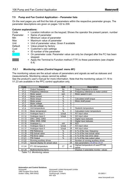
7.5.1 Monitoring values (Control keypad: menu M1)<br />
The monitoring values are the actual values of parameters and signals as well as statuses and<br />
measurements. Monitoring values cannot be edited.<br />
See the product's user's manual for more information. Note that the monitoring values V1.18 to<br />
V1.23 are available in the PFC control application only.<br />
Code Parameter Unit ID Description<br />
V1.1 Output frequency Hz 1 Output frequency to motor<br />
V1.2 Frequency reference Hz 25 Frequency reference to motor control<br />
V1.3 Motor speed rpm 2 Motor speed in rpm<br />
V1.4 Motor current A 3<br />
V1.5 Motor torque % 4 Calculated shaft torque<br />
V1.6 Motor power % 5 Motor shaft power<br />
V1.7 Motor voltage V 6<br />
V1.8 DC link voltage V 7<br />
V1.9 Unit temperature °C 8 Heatsink temperature<br />
V1.10 Motor temperature % 9 Calculated motor temperature<br />
V1.11 Analogue input 1 V/mA 13 AI1 input value<br />
V1.12 Analogue input 2 V/mA 14 AI2 input value<br />
V1.13 DIN1, DIN2, DIN3 15 Digital input statuses<br />
V1.14 DIN4, DIN5, DIN6 16 Digital input statuses<br />
V1.15 Analogue I out mA 26 AO1<br />
V1.16 Analogue input 3 V/mA 27 AI3 input value<br />
V1.17 Analogue input 4 V/mA 28 AI4 input value<br />
V1.18 PID Reference % 20 In % of the max. frequency<br />
V1.19 PID Actual value % 21 In % of the max actual value<br />
V1.20 PID Error value % 22 In % of the max error value<br />
V1.21 PID Output % 23 In % of the max output value<br />
V1.22 Running auxiliary drives 30 Number of running auxiliary drives<br />
V1.23 Special display for actual value 29 See parameters 2.9.29 to 2.9.31<br />
V1.24 PT-100 temperature Cº 42<br />
Highest temperature of used PT100<br />
inputs<br />
G1.25 Multimonitoring items Displays 3 selectable monitor. values<br />
Table 7-2. Monitoring values<br />
Automation and Control Solutions<br />
Honeywell<br />
Honeywell Limited-Honeywell Limitée<br />
1985 Douglas Drive North 35 Dynamic Drive<br />
Golden Valley, MIN 55422 Scarborough, Ontario <strong>63</strong>-<strong>2600</strong>-1<br />
MIV 4Z9<br />
www.honeywell.com