NXS Form 63-2600, Users Manual, Technical Data - CONTROL ...
NXS Form 63-2600, Users Manual, Technical Data - CONTROL ...
NXS Form 63-2600, Users Manual, Technical Data - CONTROL ...
- No tags were found...

You also want an ePaper? Increase the reach of your titles
YUMPU automatically turns print PDFs into web optimized ePapers that Google loves.
Honeywell PID Control Application 51<br />
5.4 PID Application – Parameter lists<br />
On the next pages you will find the lists of parameters within the respective parameter groups. The<br />
parameter descriptions are given on pages 122 to 209.<br />
Column explanations:<br />
Code = Location indication on the keypad; Shows the operator the present param. number<br />
Parameter = Name of parameter<br />
Min = Minimum value of parameter<br />
Max = Maximum value of parameter<br />
Unit = Unit of parameter value; Given if available<br />
Default = Value preset by factory<br />
Cust = Customer’s own setting<br />
ID<br />
= ID number of the parameter<br />
= In parameter row: Use TTF method to program these parameters.<br />
= On parameter code: Parameter value can only be changed after the FC has been<br />
stopped.<br />
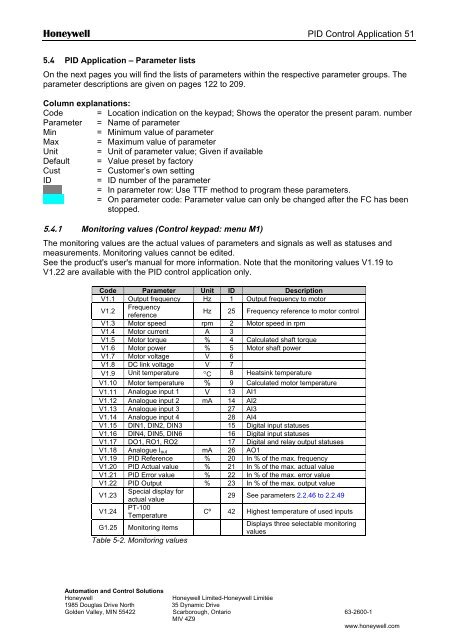
5.4.1 Monitoring values (Control keypad: menu M1)<br />
The monitoring values are the actual values of parameters and signals as well as statuses and<br />
measurements. Monitoring values cannot be edited.<br />
See the product's user's manual for more information. Note that the monitoring values V1.19 to<br />
V1.22 are available with the PID control application only.<br />
Code Parameter Unit ID Description<br />
V1.1 Output frequency Hz 1 Output frequency to motor<br />
V1.2<br />
Frequency<br />
reference<br />
Hz 25 Frequency reference to motor control<br />
V1.3 Motor speed rpm 2 Motor speed in rpm<br />
V1.4 Motor current A 3<br />
V1.5 Motor torque % 4 Calculated shaft torque<br />
V1.6 Motor power % 5 Motor shaft power<br />
V1.7 Motor voltage V 6<br />
V1.8 DC link voltage V 7<br />
V1.9 Unit temperature °C 8 Heatsink temperature<br />
V1.10 Motor temperature % 9 Calculated motor temperature<br />
V1.11 Analogue input 1 V 13 AI1<br />
V1.12 Analogue input 2 mA 14 AI2<br />
V1.13 Analogue input 3 27 AI3<br />
V1.14 Analogue input 4 28 AI4<br />
V1.15 DIN1, DIN2, DIN3 15 Digital input statuses<br />
V1.16 DIN4, DIN5, DIN6 16 Digital input statuses<br />
V1.17 DO1, RO1, RO2 17 Digital and relay output statuses<br />
V1.18 Analogue I out mA 26 AO1<br />
V1.19 PID Reference % 20 In % of the max. frequency<br />
V1.20 PID Actual value % 21 In % of the max. actual value<br />
V1.21 PID Error value % 22 In % of the max. error value<br />
V1.22 PID Output % 23 In % of the max. output value<br />
V1.23<br />
Special display for<br />
actual value<br />
29 See parameters 2.2.46 to 2.2.49<br />
V1.24<br />
PT-100<br />
Temperature<br />
Cº 42 Highest temperature of used inputs<br />
G1.25 Monitoring items<br />
Displays three selectable monitoring<br />
values<br />
Table 5-2. Monitoring values<br />
Automation and Control Solutions<br />
Honeywell<br />
Honeywell Limited-Honeywell Limitée<br />
1985 Douglas Drive North 35 Dynamic Drive<br />
Golden Valley, MIN 55422 Scarborough, Ontario <strong>63</strong>-<strong>2600</strong>-1<br />
MIV 4Z9<br />
www.honeywell.com