NXS Form 63-2600, Users Manual, Technical Data - CONTROL ...
NXS Form 63-2600, Users Manual, Technical Data - CONTROL ...
NXS Form 63-2600, Users Manual, Technical Data - CONTROL ...
- No tags were found...

Create successful ePaper yourself
Turn your PDF publications into a flip-book with our unique Google optimized e-Paper software.
Honeywell Basic Application 9<br />
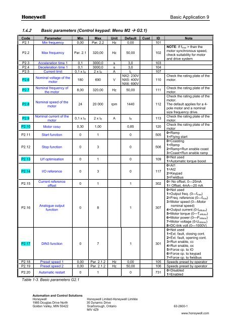
1.4.2 Basic parameters (Control keypad: Menu M2 G2.1)<br />
Code Parameter Min Max Unit Default Cust ID Note<br />
P2.1 Min frequency 0,00 Par. 2.2 Hz 0,00 101<br />
P2.2 Max frequency Par. 2.1 320,00 Hz 50,00 102<br />
P2.3 Acceleration time 1 0,1 3000,0 s 3,0 103<br />
P2.4 Deceleration time 1 0,1 3000,0 s 3,0 104<br />
P2.5 Current limit 0,1 x I H 2 x I H A I L 107<br />
P2.6<br />
Nominal voltage of the<br />
motor<br />
180 690 V<br />
NX2: 230V<br />
NX5: 400V<br />
NX6: 690V<br />
110<br />
NOTE: If f max > than the<br />
motor synchronous speed,<br />
check suitability for motor<br />
and drive system<br />
Check the rating plate of the<br />
motor.<br />
P2.7<br />
Nominal frequency of<br />
Check the rating plate of the<br />
8,00 320,00 Hz 50,00 111<br />
the motor<br />
motor.<br />
Check the rating plate of the<br />
P2.8<br />
motor.<br />
Nominal speed of the<br />
24 20 000 rpm 1440 112 The default applies for a 4-<br />
motor<br />
pole motor and a nominal<br />
size frequency drive.<br />
P2.9<br />
Nominal current of the<br />
Check the rating plate of the<br />
0,1 x I<br />
motor<br />
H 2 x I H A I H 113<br />
motor.<br />
P2.10 Motor cosϕ 0,30 1,00 0,85 120<br />
Check the rating plate of the<br />
motor<br />
P2.11 Start function 0 1 0 505<br />
0=Ramp<br />
1=Flying start<br />
P2.12 Stop function 0 3 0 506<br />
0=Coasting<br />
1=Ramp<br />
2=Ramp+Run enable coast<br />
3=Coast+Run enable ramp<br />
P2.13 U/f optimisation 0 1 0 109<br />
0=Not used<br />
1=Automatic torque boost<br />
P2.14 I/O reference 0 3 0 117<br />
0=AI1<br />
1=AI2<br />
2=Keypad<br />
3=Fieldbus<br />
P2.15<br />
Current reference<br />
0= No offset, 0—20mA<br />
0 1 1 302<br />
offset<br />
1= Offset, 4mA—20 mA<br />
0=Not used<br />
1=Output freq. (0—f max )<br />
2=Freq. reference (0—f max )<br />
3=Motor speed (0—Motor<br />
P2.16<br />
Analogue output<br />
nominal speed)<br />
0 8 1 307<br />
function<br />
4=Output current (0-I nMotor )<br />
5=Motor torque (0—T nMotor )<br />
6=Motor power (0—P nMotor )<br />
7=Motor voltage (0-U nMotor )<br />
8=DC-link volt (0—1000V)<br />
P2.17 DIN3 function 0 7 1 301<br />
0=Not used<br />
1=Ext. fault, closing cont.<br />
2=Ext. fault, opening cont.<br />
3=Run enable, cc<br />
4=Run enable, oc<br />
5=Force cp. to IO<br />
6=Force cp. to keypad<br />
7=Force cp. to fieldbus<br />
P2.18 Preset speed 1 0,00 Par. 2.1.2 Hz 0,00 105 Speeds preset by operator<br />
P2.19 Preset speed 2 0,00 Par. 2.1.2 Hz 50,00 106 Speeds preset by operator<br />
P2.20 Automatic restart 0 1 0 731<br />
0=Disabled<br />
1=Enabled<br />
Table 1-3. Basic parameters G2.1<br />
Automation and Control Solutions<br />
Honeywell<br />
Honeywell Limited-Honeywell Limitée<br />
1985 Douglas Drive North 35 Dynamic Drive<br />
Golden Valley, MIN 55422 Scarborough, Ontario <strong>63</strong>-<strong>2600</strong>-1<br />
MIV 4Z9<br />
1<br />
www.honeywell.com