- Page 1 and 2:
Cooper TP Workshop Manual_Scant:Lay
- Page 3:
scan_wsm_iss5 front page_outlines.p
- Page 6 and 7:
CUSTOMER SERVICE POLICYCooper Secur
- Page 8 and 9:
Control PanelsControl Panelswww.coo
- Page 10 and 11:
9448+/9448ESINTRODUCTIONThe 9448+ a
- Page 13:
Main Connector 9448+ Wiring Example
- Page 17 and 18:
9448+/9448ESEngineer Program Comman
- Page 19 and 20:
9448+/9448ESEngineer Walk TestEngin
- Page 21 and 22:
9449Installation and User GuideComp
- Page 23 and 24:
9449 InputsInputsTellback/RedCare r
- Page 25 and 26:
9449 Wiring ExampleFigure 3. Wiring
- Page 27 and 28:
9449 Engineer Program Command List1
- Page 29 and 30:
9449 Engineer Program Command ListT
- Page 31 and 32:
9449 Restoring Factory DefaultsRest
- Page 33 and 34:
9449 Printing the LogPrinting the L
- Page 35 and 36:
9449 Fault Finding496329 Issue 1 15
- Page 37 and 38:
9500Installation and User GuideComp
- Page 39 and 40:
9500 Technical Specificationof the
- Page 41 and 42:
9500 WiringFigure 4. Standard LIM P
- Page 43 and 44:
9500 WiringFigure 8. Remote PSU/LIM
- Page 45 and 46:
9500 WiringFigure 12. 9576 Interfac
- Page 47 and 48:
9500 Engineering Program Commands9.
- Page 49 and 50:
9500 Engineering Program Commands49
- Page 51 and 52:
9500 Leaving Engineering ModeLeavin
- Page 53 and 54:
9500 Refreshing the Systemprevent a
- Page 55 and 56:
9500 9500 Log EventsWT tamper ####
- Page 57 and 58:
9500 User CommandsLIM ### shuntedRe
- Page 59 and 60:
9600/9610Installation and User Guid
- Page 61 and 62:
9600/9610Addressing KeypadsBefore p
- Page 63 and 64:
9600/9610WiringOBSOLETE PRODUCTFigu
- Page 65 and 66:
9600/9610 WiringFigure 3. 9625 Keyp
- Page 67 and 68:
9600/9610 DefaultsDefaultsFUNCTIOND
- Page 69 and 70:
9600/9610 Programming ChartOBSOLETE
- Page 71 and 72:
9600/9610 Programming ChartOBSOLETE
- Page 73 and 74:
9600/9610 Entering Engineer Mode fr
- Page 75 and 76:
9600/9610 Error MessagesSYSTEM FAUL
- Page 77 and 78:
9600/9610 Invalid Access Code Enter
- Page 79 and 80:
9066Installation GuideCompatible Eq
- Page 81 and 82:
9066Note: When installing the modul
- Page 83 and 84:
9800+Installation and User GuideCom
- Page 85 and 86:
9800+ 9827 Keypad AddressingControl
- Page 87 and 88:
9800+ Wiring KeypadsWiring KeypadsA
- Page 89 and 90:
9800+ CommunicationsCommunicationsT
- Page 91 and 92:
9800+ Engineering Program CommandsE
- Page 93 and 94:
9800+ Engineering Program CommandsT
- Page 95 and 96:
9800+ Re-entering Programming ModeR
- Page 97 and 98:
9800+ TestingKeypad and Event Log D
- Page 99 and 100:
808Installation and User GuideCompa
- Page 101 and 102:
808GeneralOperating temperatureHumi
- Page 103 and 104:
808 Enabling/Disabling Keys, Displa
- Page 105 and 106:
808 Wiring Detector ZonesEnd Statio
- Page 107 and 108:
808 Finding Menu Items4. Press 0.Th
- Page 109 and 110:
808 Programming ChartA09:print opti
- Page 111 and 112:
808 Zone ProgrammingThe display sho
- Page 113 and 114:
808 Leaving Programming ModeFigure
- Page 115 and 116:
808 Resetting Customer and Installe
- Page 117 and 118:
808 Fault FindingMenu 50: Program o
- Page 119 and 120:
808 Operating the SystemThe Supervi
- Page 121 and 122:
816Installation and User GuideCompa
- Page 123 and 124:
816 Technical SpecificationThe keyp
- Page 125 and 126:
816InstallationKeypadsProgramming K
- Page 127 and 128:
816 Wiring KeypadsFigure 3. 816 Mai
- Page 129 and 130:
816 Programming2k2 EOL4k7Alarm cont
- Page 131 and 132:
816 Programming Chart00:programsyst
- Page 133 and 134:
816 Changing Menu ItemsChanging Men
- Page 135 and 136:
816 Re-entering Programming Mode3.
- Page 137 and 138:
816 Programming ZonesNote: At this
- Page 139 and 140:
816 Fault FindingMenu 40: Program m
- Page 141 and 142:
816 User FacilitiesLEVELSET O/P 3Me
- Page 143 and 144:
8136UK-50/75Installation and User G
- Page 145 and 146:
8136 KeypadsKeypadsThe 931 KeypadTh
- Page 147 and 148:
8136 BatterySiren= 750mA.Batt (reve
- Page 149 and 150: 8136 Wiring8. Press ‘Menu’.The
- Page 151 and 152: 8136 Wiring FSL DetectorsWiring FSL
- Page 153 and 154: 8136ProgrammingInitial Power UpBatt
- Page 155 and 156: 8136 Programming Chart00:PROGRAMSYS
- Page 157 and 158: 8136 Changing Menu ItemsChanging Me
- Page 159 and 160: 8136 Re-entering Programming Mode2.
- Page 161 and 162: 8136 Programming for IDIS5. Open th
- Page 163 and 164: 8136 Programming for IDISOR: For in
- Page 165 and 166: 8136 Factory DefaultsProgramming Zo
- Page 167 and 168: 8136 Working with Menu 61:Menu 62:M
- Page 169 and 170: 8136 Connecting to a Remote PC for
- Page 171 and 172: 8136 Fault FindingThe display shows
- Page 173 and 174: 8136 Configuration Checking Error M
- Page 175 and 176: 8136 Simple Test MethodIDIS Fault F
- Page 177 and 178: 8136 Thorough Test MethodTable 3. I
- Page 179 and 180: 8136 Fitting a PSU2. If faults are
- Page 181 and 182: 8136 User FacilitiesElectrical Nois
- Page 183 and 184: 8136 Installer SettingUsers can rep
- Page 185 and 186: 8136 User menu ChartAccess Code +Me
- Page 187 and 188: IDISReference GuideCompatible Equip
- Page 189 and 190: IDIS 901To program IDIS detectors s
- Page 191 and 192: IDIS 903WiringOptionalRemote PSUCon
- Page 193 and 194: IDIS 904WiringOptionalRemote PSUCon
- Page 195 and 196: IDIS 905WiringControl PanelIDIS Exp
- Page 197 and 198: IDIS 906Dimensionsh x w x d 210 x 2
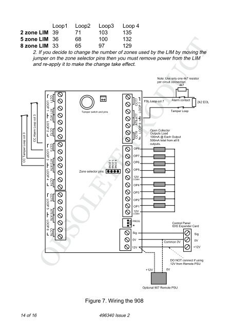
- Page 199: Introduction908 IDIS LIM INSTALLATI
- Page 203 and 204: 95EN/85EN/65ENInstallation and Prog
- Page 205 and 206: 95EN, 85EN, 65EN1. IntroductionTabl
- Page 207 and 208: 95EN, 85EN, 65ENSystem LayoutNetwor
- Page 209 and 210: 95EN, 85EN, 65ENCompatible DevicesF
- Page 211 and 212: 95EN, 85EN, 65ENNote: Before connec
- Page 213 and 214: 95EN, 85EN, 65ENBell Trigger:Switch
- Page 215 and 216: 95EN, 85EN, 65ENLEDs (95EN and 85EN
- Page 217 and 218: A B C D EREMOTE NETWORK 1USBLED4ENG
- Page 219 and 220: 95EN, 85EN, 65ENFitting and Wiring
- Page 221 and 222: 95EN, 85EN, 65ENCONTROLPANEL100m ma
- Page 223 and 224: 95EN, 85EN, 65EN5. Voltage drop to
- Page 225 and 226: 95EN, 85EN, 65ENFigure 11. Reducing
- Page 227 and 228: 95EN, 85EN, 65ENBy default, alarm c
- Page 229 and 230: 95EN, 85EN, 65ENControl Panel Netwo
- Page 231 and 232: 95EN, 85EN, 65EN• Serial connecti
- Page 233 and 234: 95EN, 85EN, 65EN• If you connect
- Page 235 and 236: 95EN, 85EN, 65ENTypical Connections
- Page 237 and 238: 95EN, 85EN, 65EN12Vdc Auxiliary Pow
- Page 239 and 240: 95EN, 85EN, 65ENAn engineer's keypa
- Page 241 and 242: 95EN, 85EN, 65ENKEYPAD INSTALLATION
- Page 243 and 244: 95EN, 85EN, 65ENnumber of keypads d
- Page 245 and 246: 95EN, 85EN, 65ENThe next messages s
- Page 247 and 248: 95EN, 85EN, 65ENThe Engineer Menu00
- Page 249 and 250: 95EN, 85EN, 65EN47: EN5013101= 4 Di
- Page 251 and 252:
95EN, 85EN, 65ENSettings Defaulted
- Page 253 and 254:
95EN, 85EN, 65ENPress ENT repeatedl
- Page 255 and 256:
95EN, 85EN, 65ENLog Message/Event S
- Page 257 and 258:
95EN, 85EN, 65ENLog Message/Event S
- Page 259 and 260:
95EN, 85EN, 65ENDD243: 2002 Para:6.
- Page 261 and 262:
95EN, 85EN, 65ENOption 93-2: Printi
- Page 263 and 264:
95EN, 85EN, 65EN#,## AUX FAULT Netw
- Page 265 and 266:
95EN, 85EN, 65ENoutCODE LOCKED ####
- Page 267 and 268:
95EN, 85EN, 65ENPARTITIONPartition
- Page 269 and 270:
95EN, 85EN, 65ENTX #### SUP OKTX ##
- Page 271 and 272:
95EN, 85EN, 65EN1. Make sure that n
- Page 273 and 274:
95EN, 85EN, 65EN2. Check that the t
- Page 275 and 276:
9x5xInstallation And ProgrammingGui
- Page 277 and 278:
9x5x1. INTRODUCTIONThe table below
- Page 279 and 280:
9x5xThe RFX radio expander can hand
- Page 281 and 282:
9x5x9954 20mA typical, 30mA maximum
- Page 283 and 284:
9x5x9752 Control Unit PCB LayoutFig
- Page 285 and 286:
9x5x9651 Control Unit PCB LayoutFig
- Page 287 and 288:
9x5x8-core 7/0.2 cableNumber of ite
- Page 289 and 290:
9x5xbottom edge of the keypad.2. Se
- Page 291 and 292:
9x5x4. Re-fit the front cover of th
- Page 293 and 294:
9x5xFigure 14 shows the connections
- Page 295 and 296:
9x5xElmdene Rapier 300, 4000, 5000,
- Page 297 and 298:
9x5xThe wiring resistance of the ca
- Page 299 and 300:
9x5x• By a specified resistance v
- Page 301 and 302:
9x5x71234560V 12V CLK DATA891011121
- Page 303 and 304:
9x5xProgramming OutputsControl unit
- Page 305 and 306:
9x5x"Dynamic" test calls occur 24 h
- Page 307 and 308:
9x5xConnecting the Telephone LineCo
- Page 309 and 310:
9x5x12 Power supply 5V13 CH 6 (see
- Page 311 and 312:
9x5xOP1-Fire(01)Pin 1FireOP2-PA (Ho
- Page 313 and 314:
9x5xNote: If any 24-hour, Fire, PA
- Page 315 and 316:
9x5x4. Press X repeatedly until the
- Page 317 and 318:
9x5xCommandKey in:b = Zone attribut
- Page 319 and 320:
9x5xCommandKey in:38 System Tamper3
- Page 321 and 322:
9x5xCommandKey in:61 Level/Partitio
- Page 323 and 324:
9x5xCommandKey in:75 Level/Partitio
- Page 325 and 326:
9x5xCommandKey in:90 Event Log 90yn
- Page 327 and 328:
9x5xCommandKey in:123 Report Restor
- Page 329 and 330:
9x5xCommand33 Pulse Set 434 Pulse U
- Page 331 and 332:
9x5xCommandC191-198 are for program
- Page 333 and 334:
9x5xCommandKey in:C211-218: program
- Page 335 and 336:
9x5xFORBI INTERFACE TAMPER TA 137FO
- Page 337 and 338:
9x5xTD (Time and day) RESET JT 625T
- Page 339 and 340:
9x5xProgramming for ComplianceUse t
- Page 341 and 342:
9x5xCommand Grade 1/2 Grade 3 Notes
- Page 343 and 344:
9x5xPartition A B C DExit Mode C39
- Page 345 and 346:
9x5xChime tone when the printer is
- Page 347 and 348:
9x5xKeypad Display Printed (9853 on
- Page 349 and 350:
9x5xcommunication system, from the
- Page 351 and 352:
RadioRadiowww.coopersecurity.co.ukA
- Page 353 and 354:
500r+IntroductionThe 500r+ is a pro
- Page 355 and 356:
500r+WiringExternal BellFigure 9 sh
- Page 357 and 358:
500r+ProgrammingInitial Power UpNot
- Page 359 and 360:
Program Commands 500r+The control u
- Page 361 and 362:
Changing the User Code 500r+4. Remo
- Page 363 and 364:
500r+The system goes back to progra
- Page 365 and 366:
14 of 14 496361 Issue 1
- Page 367 and 368:
502502r Watch/PendantIntroductionTh
- Page 369 and 370:
Technical Specification 509Technica
- Page 371 and 372:
525525r Remote Setting DeviceIntrod
- Page 373 and 374:
535Connecting External Door Contact
- Page 375 and 376:
546546 Test TransmitterIntroduction
- Page 377 and 378:
4600IntroductionThe 4600 electronic
- Page 379 and 380:
Initial Power Up 4600Figure 2. Sett
- Page 381 and 382:
Engineering Program Commands 4600Zo
- Page 383 and 384:
Leaving Programming Mode 4600Leavin
- Page 385 and 386:
Fault Finding 4600Remote setting tr
- Page 387 and 388:
12 of 12 496368 Issue 1
- Page 389 and 390:
RangeGeneralTransmitter range depen
- Page 391 and 392:
4601The pendants must be coded to m
- Page 393 and 394:
4602Re-assemblyRefit the lid of the
- Page 395 and 396:
46024612Set switches 1-10 to the si
- Page 397 and 398:
4603The 4603-60 operates on the DTI
- Page 399 and 400:
4603Technical SpecificationThis sec
- Page 401 and 402:
4604Figure 9. 4603 Mode 4The unit t
- Page 403 and 404:
46044618/9Set switches 1 to 8 to th
- Page 405 and 406:
4605Technical SpecificationDimensio
- Page 407 and 408:
4606Final CommissioningAfter coding
- Page 409 and 410:
4606Final CommissioningSwitch on th
- Page 411 and 412:
4608Figure 16. 4608 PB Layout24 of
- Page 413 and 414:
4608Figure 18. Wide Angle and Curta
- Page 415 and 416:
4608TestingZone Locator TestFigure
- Page 417 and 418:
46244612Switches 1 to 10 on the rec
- Page 419 and 420:
4624Note 1. If the transmitter is u
- Page 421 and 422:
34 of 34 496372 Issue 1
- Page 423 and 424:
4612IntroductionThe 4612 is a two c
- Page 425 and 426:
Single Channel Mode 4612Mode Switch
- Page 427 and 428:
4612Sensor/Transmitter TestsTESTING
- Page 429 and 430:
4618IntroductionThe 46RX family of
- Page 431 and 432:
Technical Description 4618The recei
- Page 433 and 434:
Outputs 4618OutputsFront PanelEach
- Page 435 and 436:
External Reset Connection 4618Exter
- Page 437 and 438:
Setting Up Receivers and Transmitte
- Page 439 and 440:
Allocating Transmitters to Modes 46
- Page 441 and 442:
Modes 9 to 13, and 19 46185 1 & 2 L
- Page 443 and 444:
4618Mode 20 and 21 (Group Modes)Mod
- Page 445 and 446:
18 of 20 496371 Issue 14618
- Page 447 and 448:
20 of 20 496371 Issue 14618
- Page 449 and 450:
4690INTRODUCTIONA radio link’s pe
- Page 451 and 452:
Checking that the Channel is Clear
- Page 453 and 454:
Interference 4690Neighbouring Syste
- Page 455 and 456:
AerialsAerial TypesIntroductionMode
- Page 457 and 458:
4 of 4 496382 Issue 1Aerials
- Page 459 and 460:
Overview1. Introduction7510rThe 751
- Page 461 and 462:
Opening the CaseTo gain access to t
- Page 463 and 464:
7510r1. Mains cable strain relief c
- Page 465 and 466:
7510rElectromagnetic CompatibilityI
- Page 467 and 468:
3. Connect to MainsFigure 8 shows t
- Page 469 and 470:
6. Remote Loudspeaker/Microphone (O
- Page 471 and 472:
7510rLower the control unit body on
- Page 473 and 474:
The Programming MenuDetectorsAdd/de
- Page 475 and 476:
7510rLetters assigned to keys5. Use
- Page 477 and 478:
INTERMEDIATEEvent SIA Code CID Code
- Page 479 and 480:
7510rLoudspeakerPress On/Off to pla
- Page 481 and 482:
24 of 24 Issue 17510r
- Page 483 and 484:
MRNode1. IntroductionThe MRNode is
- Page 485 and 486:
MRNodeThis product is complies with
- Page 487 and 488:
MRNodeDO site the MRNode:a) In a co
- Page 489 and 490:
MRNodeTo enter learn mode while pow
- Page 491 and 492:
MRNode5. The display updates the si
- Page 493 and 494:
1. IntroductionThe RFX8 and RFX16 a
- Page 495 and 496:
RFXAll the transmitters designed to
- Page 497 and 498:
RFXFitting the RFXThe following ins
- Page 499 and 500:
RFXThe RFX gives a short beep and a
- Page 501 and 502:
RFXJammingWith the jamming response
- Page 503 and 504:
770rIntroductionThe 770r Wireless A
- Page 505 and 506:
770rPhysical LayoutOpen the case by
- Page 507 and 508:
770rDipswitches1. OFF = IR Learning
- Page 509 and 510:
770rNext to electronic equipment, p
- Page 511 and 512:
770r3. Common is fl oating. Do not
- Page 513 and 514:
770rMenu Command ReferenceLearn Tra
- Page 515 and 516:
770r1. Press SELECT repeatedly unti
- Page 517 and 518:
770r2. Press SET.The bottom LED sho
- Page 519 and 520:
Commissioning The 770rThis section
- Page 521 and 522:
770r8. Leave menu 1, and then leave
- Page 523 and 524:
770r1 2 34 5 67 8 90 #Figure 8.Oper
- Page 525 and 526:
770rSounder Connections(powered by
- Page 527 and 528:
770r12. Connect the transmitter Mod
- Page 529 and 530:
770r4. Use menu 1 to learn any tran
- Page 531 and 532:
30 of 30 Issue 1770r
- Page 533 and 534:
701rIntroductionThe 701REUR-50/60 a
- Page 535 and 536:
701rON NO ACCOUNT USE AN ACETIC ACI
- Page 537 and 538:
702rIntroductionThe 702 Watch/Penda
- Page 539 and 540:
702rFitting the Wrist StrapThread t
- Page 541 and 542:
703r1. INTRODUCTIONThe 703EUR-00 is
- Page 543 and 544:
4 of 18703rInputsConnectorsThe 703
- Page 545 and 546:
703rother radio equipment, CAT 5 da
- Page 547 and 548:
703r4. PROGRAMMINGIn order to put t
- Page 549 and 550:
Command FunctionoP Set mode to one
- Page 551 and 552:
703ralarm and tamper for device two
- Page 553 and 554:
703r14 of 18A Roller Shutter Sensor
- Page 555 and 556:
16 of 18703r3. Press Set.4. Strike
- Page 557 and 558:
703rPower Fail SignallingThe 703r c
- Page 559 and 560:
705rDescriptionThe 705r dual functi
- Page 561 and 562:
4 of 4 Issue 1705r
- Page 563 and 564:
IntroductionThe 706rEUR-00 has an i
- Page 565 and 566:
706rServicingThe internal lithium p
- Page 567 and 568:
710r211. Aerial2. Activity LED3. Pu
- Page 569 and 570:
710r7500 7510 9960 RFX16RFX08762 76
- Page 571 and 572:
714rIntroductionThe 714r Passive In
- Page 573 and 574:
714rMount the backThe 714r is desig
- Page 575 and 576:
714r4. Make sure the panel receives
- Page 577 and 578:
8 of 8 Issue 1714r
- Page 579 and 580:
IntroductionThe 720r Smoke Detector
- Page 581 and 582:
720rthe alarm is installed on a wal
- Page 583 and 584:
720rUnder the test button, there is
- Page 585 and 586:
2 of 2 Issue 1723r
- Page 587 and 588:
IntroductionThe 734rEUR-00 and -01
- Page 589 and 590:
734rInstallationSitingDo NOT mount
- Page 591 and 592:
734rBoth variants of the 734r provi
- Page 593 and 594:
734r2. Operate the roller shutter s
- Page 595 and 596:
10 of 10 Issue 1734r
- Page 597 and 598:
IntroductionThe 738r Radio Spyder i
- Page 599 and 600:
738rPreparing for Installation1. Op
- Page 601 and 602:
738rFigure 5. Figure 6.Figure 7. Fi
- Page 603 and 604:
739r1. Aerial2. Invert input.3. LED
- Page 605 and 606:
739rProgrammingTo program the 739r
- Page 607 and 608:
762r1. INTRODUCTIONThe 762r is a tw
- Page 609 and 610:
762r1234567891011121351 External an
- Page 611 and 612:
762rInputsRadioThe 762rEUR-50 conta
- Page 613 and 614:
762rSiting The ReceiverDo site the
- Page 615 and 616:
762rNote: Make sure you remove all
- Page 617 and 618:
762rTo enter programming while the
- Page 619 and 620:
762rLearning DetectorsThe 762r lear
- Page 621 and 622:
762r3. Press Set.The display altern
- Page 623 and 624:
762r5. Press Set.The display shows
- Page 625 and 626:
762rSupervision enable on the 703r
- Page 627 and 628:
762r6. TestingYou can measure signa
- Page 629 and 630:
24 of 24 Issue 1762r
- Page 631 and 632:
768r/769r1. INTRODUCTIONThe 768r is
- Page 633 and 634:
768r/769rPhysical LayoutThe 768r/76
- Page 635 and 636:
768r/769rControls and DisplaysFront
- Page 637 and 638:
768r/769rChannel A andChannel BComm
- Page 639 and 640:
768r/769rAllocating Transmitters an
- Page 641 and 642:
768r/769r8. Take the case down, dri
- Page 643 and 644:
768r/769rConnecting the Optional 8-
- Page 645 and 646:
768r/769r2. Press Select.The displa
- Page 647 and 648:
768r/769rLearning DetectorsThe 768r
- Page 649 and 650:
768r/769rYou may wish to learn seve
- Page 651 and 652:
768r/769r2. Press Select until the
- Page 653 and 654:
768r/769rTo disable infra-red learn
- Page 655 and 656:
768r/769r12 Reserved for future use
- Page 657 and 658:
768r/769r4. Close the case lid.The
- Page 659 and 660:
790rIntroductionThe 790r Radio Stre
- Page 661 and 662:
790rSingleDisplays the signal stren
- Page 663 and 664:
790rTransmitter (see above). Set th
- Page 665 and 666:
2 of 2RFX
- Page 667 and 668:
8400/8440/9056Installation GuideCom
- Page 669 and 670:
8400/8440/9056 IntroductionThe unit
- Page 671 and 672:
8400/8440/9056Technical Specificati
- Page 673 and 674:
8400/8440/9056 TestingApply power (
- Page 675 and 676:
660/960Installation GuideCompatible
- Page 677 and 678:
660/960Physical LayoutFigure 1. 660
- Page 679 and 680:
660/960 Connecting to the Telephone
- Page 681 and 682:
660/960 Recording Speech MessagesSt
- Page 683 and 684:
660/960 Called Party ControlsADVANC
- Page 685 and 686:
660/960 Input to Telephone Number M
- Page 687 and 688:
660/960 Call Clearingprevent the co
- Page 689 and 690:
660/960 Output Control49 0 # No per
- Page 691 and 692:
7400 Remote Reset TerminalInstallat
- Page 693 and 694:
7400 OperationFigure 2. Connection
- Page 695 and 696:
7400 ProgrammingProgrammingWith the
- Page 697 and 698:
8740, 8750Installation GuideCompati
- Page 699 and 700:
8740, 8750Figure 2) Internal Ribbon
- Page 701 and 702:
8740, 87507. Present the back of th
- Page 703 and 704:
8841Installation and ProgrammingGui
- Page 705 and 706:
88411211. Screw positions.2. Batter
- Page 707 and 708:
884112. Seat the back of the case i
- Page 709 and 710:
8841• A Home Message and a text m