Zbornik radova Koridor 10 - Kirilo SaviÄ
Zbornik radova Koridor 10 - Kirilo SaviÄ
Zbornik radova Koridor 10 - Kirilo SaviÄ

Create successful ePaper yourself
Turn your PDF publications into a flip-book with our unique Google optimized e-Paper software.
3rd International Scientific and Professional Conference<br />
CORRIDOR <strong>10</strong> - a sustainable way of integrations<br />
Mach number range is 0.1 to 0.6 with running only by fan, and 0.6 to 0.8 with fan and injector included.<br />
Reynolds number is up to 2.3 million/m, and stagnation pressure is in range from 1.0 to 1.52 bar. Run<br />
time is unlimited with fan power only, and up to 120s with injector system included.<br />
The wind tunnel is equipped with: six-component external TEM balance, Multi-component internal<br />
strain gauge balances of VTI, FFA and ABLE production, Pressure scanning system: five S3 or D9<br />
Scanivalves (230 pressure taps), Dynamic stability derivatives rigs for pitch/yaw/roll, Air intake testing<br />
rig, data acquisition system, Data acquisition computer, Control computer, Data reduction computer.<br />
Main goal of testing runs is to determine the pressure distribution on the high-speed train model in the<br />
configuration of single drive on open track.<br />
2.1 Model description<br />
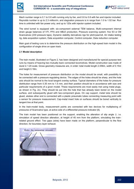
The train model, illustrated on Figure 2, has been designed and manufactured for special purpose test<br />
runs by means of heaving two mutually back connected locomotives. Model construction was made of<br />
dural in 1:20 scale. Gross geometry measures are, in order: total model length 2.056m, width of 0.15m<br />
and height 0.18m.<br />
The holes for measurement of pressure distribution on the model should be small, with possibility to<br />
be connected with a pressure-regulating device. The edges of the holes should be sharp, and the hole<br />
axis should be normal to the local tangent overlay surface. Typical diameters of the holes for pressure<br />
distribution range from 0.35 mm to 1.5 mm, and their position should be in accordance with size and<br />
particular requirements of a given model. These requirements are most easily met using metal plugs,<br />
as shown in Fig. 2c). They should be put into the hole that has already been bored on the model<br />
surface, and subsequently glued with two-component glues. On cap support, metal tube should be<br />
glued, wtubes other end is connected with a plastic pneumatic tubes connecting measuring point with<br />
a sensor for pressure measurement. Cap-metal insert hole on surfaces should be bored vertically to<br />
tangent line at that point.<br />
In the train-model body, measurement points are connected with two devices for multiplexing of<br />
pressures of Scanivalve type, at active side of a differential pressure-indicator [4].<br />
The train model has been positioned on the support, enabling the alteration of slip angle , i.e.<br />
simulation of speed direction alteration, at height of 40 mm from the platform, simulating the trainrelated<br />
ground effect. Two gaps (slots) have been made on the platform, perpendicular to the flow<br />
direction, for boundary layer exhaust.<br />
Holes for measuring pressure<br />
distribution<br />
a)<br />
Belgrade, 2012 222