

Geode GXLV Processor Series Low Power Integrated x86 Solutions
Geode GXLV Processor Series Low Power Integrated x86 Solutions
Geode GXLV Processor Series Low Power Integrated x86 Solutions

Create successful ePaper yourself
Turn your PDF publications into a flip-book with our unique Google optimized e-Paper software.
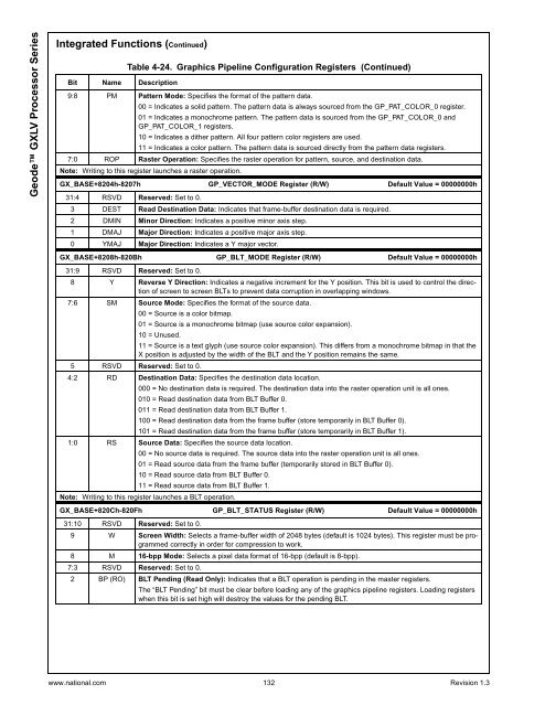
<strong>Geode</strong> <strong>GXLV</strong> <strong>Processor</strong> <strong>Series</strong><strong>Integrated</strong> Functions (Continued)Bit Name DescriptionTable 4-24. Graphics Pipeline Configuration Registers (Continued)9:8 PM Pattern Mode: Specifies the format of the pattern data.00 = Indicates a solid pattern. The pattern data is always sourced from the GP_PAT_COLOR_0 register.01 = Indicates a monochrome pattern. The pattern data is sourced from the GP_PAT_COLOR_0 andGP_PAT_COLOR_1 registers.10 = Indicates a dither pattern. All four pattern color registers are used.11 = Indicates a color pattern. The pattern data is sourced directly from the pattern data registers.7:0 ROP Raster Operation: Specifies the raster operation for pattern, source, and destination data.Note: Writing to this register launches a raster operation.GX_BASE+8204h-8207h GP_VECTOR_MODE Register (R/W) Default Value = 00000000h31:4 RSVD Reserved: Set to 0.3 DEST Read Destination Data: Indicates that frame-buffer destination data is required.2 DMIN Minor Direction: Indicates a positive minor axis step.1 DMAJ Major Direction: Indicates a positive major axis step.0 YMAJ Major Direction: Indicates a Y major vector.GX_BASE+8208h-820Bh GP_BLT_MODE Register (R/W) Default Value = 00000000h31:9 RSVD Reserved: Set to 0.8 Y Reverse Y Direction: Indicates a negative increment for the Y position. This bit is used to control the directionof screen to screen BLTs to prevent data corruption in overlapping windows.7:6 SM Source Mode: Specifies the format of the source data.00 = Source is a color bitmap.01 = Source is a monochrome bitmap (use source color expansion).10 = Unused.11 = Source is a text glyph (use source color expansion). This differs from a monochrome bitmap in that theX position is adjusted by the width of the BLT and the Y position remains the same.5 RSVD Reserved: Set to 0.4:2 RD Destination Data: Specifies the destination data location.000 = No destination data is required. The destination data into the raster operation unit is all ones.010 = Read destination data from BLT Buffer 0.011 = Read destination data from BLT Buffer 1.100 = Read destination data from the frame buffer (store temporarily in BLT Buffer 0).101 = Read destination data from the frame buffer (store temporarily in BLT Buffer 1).1:0 RS Source Data: Specifies the source data location.00 = No source data is required. The source data into the raster operation unit is all ones.01 = Read source data from the frame buffer (temporarily stored in BLT Buffer 0).10 = Read source data from BLT Buffer 0.11 = Read source data from BLT Buffer 1.Note: Writing to this register launches a BLT operation.GX_BASE+820Ch-820Fh GP_BLT_STATUS Register (R/W) Default Value = 00000000h31:10 RSVD Reserved: Set to 0.9 W Screen Width: Selects a frame-buffer width of 2048 bytes (default is 1024 bytes). This register must be programmedcorrectly in order for compression to work.8 M 16-bpp Mode: Selects a pixel data format of 16-bpp (default is 8-bpp).7:3 RSVD Reserved: Set to 0.2 BP (RO) BLT Pending (Read Only): Indicates that a BLT operation is pending in the master registers.The “BLT Pending” bit must be clear before loading any of the graphics pipeline registers. Loading registerswhen this bit is set high will destroy the values for the pending BLT.www.national.com 132 Revision 1.3


