

Geode GXLV Processor Series Low Power Integrated x86 Solutions
Geode GXLV Processor Series Low Power Integrated x86 Solutions
Geode GXLV Processor Series Low Power Integrated x86 Solutions

Create successful ePaper yourself
Turn your PDF publications into a flip-book with our unique Google optimized e-Paper software.
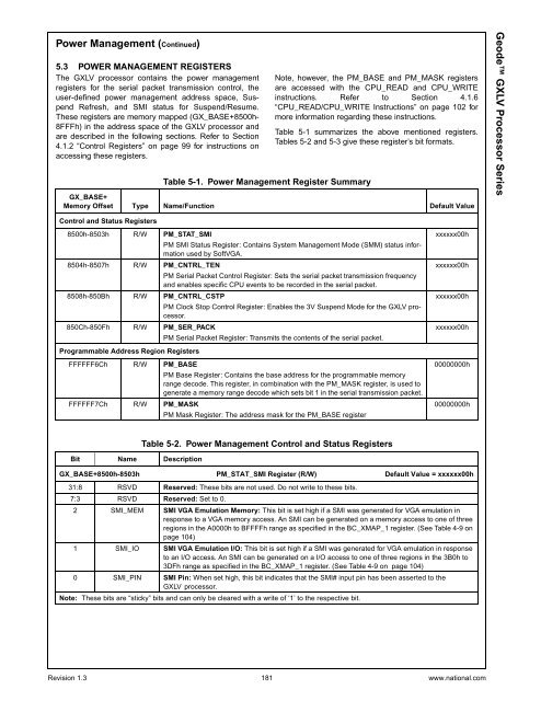
<strong>Power</strong> Management (Continued)5.3 POWER MANAGEMENT REGISTERSThe <strong>GXLV</strong> processor contains the power managementregisters for the serial packet transmission control, theuser-defined power management address space, SuspendRefresh, and SMI status for Suspend/Resume.These registers are memory mapped (GX_BASE+8500h-8FFFh) in the address space of the <strong>GXLV</strong> processor andare described in the following sections. Refer to Section4.1.2 “Control Registers” on page 99 for instructions onaccessing these registers.Table 5-1. <strong>Power</strong> Management Register SummaryNote, however, the PM_BASE and PM_MASK registersare accessed with the CPU_READ and CPU_WRITEinstructions. Refer to Section 4.1.6“CPU_READ/CPU_WRITE Instructions” on page 102 formore information regarding these instructions.Table 5-1 summarizes the above mentioned registers.Tables 5-2 and 5-3 give these register’s bit formats.GX_BASE+Memory Offset Type Name/Function Default Value<strong>Geode</strong> <strong>GXLV</strong> <strong>Processor</strong> <strong>Series</strong>Control and Status Registers8500h-8503h R/W PM_STAT_SMIPM SMI Status Register: Contains System Management Mode (SMM) status informationused by SoftVGA.8504h-8507h R/W PM_CNTRL_TENPM Serial Packet Control Register: Sets the serial packet transmission frequencyand enables specific CPU events to be recorded in the serial packet.8508h-850Bh R/W PM_CNTRL_CSTPPM Clock Stop Control Register: Enables the 3V Suspend Mode for the <strong>GXLV</strong> processor.850Ch-850Fh R/W PM_SER_PACKPM Serial Packet Register: Transmits the contents of the serial packet.xxxxxx00hxxxxxx00hxxxxxx00hxxxxxx00hProgrammable Address Region RegistersFFFFFF6Ch R/W PM_BASEPM Base Register: Contains the base address for the programmable memoryrange decode. This register, in combination with the PM_MASK register, is used togenerate a memory range decode which sets bit 1 in the serial transmission packet.FFFFFF7Ch R/W PM_MASKPM Mask Register: The address mask for the PM_BASE register00000000h00000000hBit Name DescriptionTable 5-2. <strong>Power</strong> Management Control and Status RegistersGX_BASE+8500h-8503h PM_STAT_SMI Register (R/W) Default Value = xxxxxx00h31:8 RSVD Reserved: These bits are not used. Do not write to these bits.7:3 RSVD Reserved: Set to 0.2 SMI_MEM SMI VGA Emulation Memory: This bit is set high if a SMI was generated for VGA emulation inresponse to a VGA memory access. An SMI can be generated on a memory access to one of threeregions in the A0000h to BFFFFh range as specified in the BC_XMAP_1 register. (See Table 4-9 onpage 104)1 SMI_IO SMI VGA Emulation I/O: This bit is set high if a SMI was generated for VGA emulation in responseto an I/O access. An SMI can be generated on a I/O access to one of three regions in the 3B0h to3DFh range as specified in the BC_XMAP_1 register. (See Table 4-9 on page 104)0 SMI_PIN SMI Pin: When set high, this bit indicates that the SMI# input pin has been asserted to the<strong>GXLV</strong> processor.Note: These bits are “sticky” bits and can only be cleared with a write of ‘1’ to the respective bit.Revision 1.3 181 www.national.com


