

Geode GXLV Processor Series Low Power Integrated x86 Solutions
Geode GXLV Processor Series Low Power Integrated x86 Solutions
Geode GXLV Processor Series Low Power Integrated x86 Solutions

You also want an ePaper? Increase the reach of your titles
YUMPU automatically turns print PDFs into web optimized ePapers that Google loves.
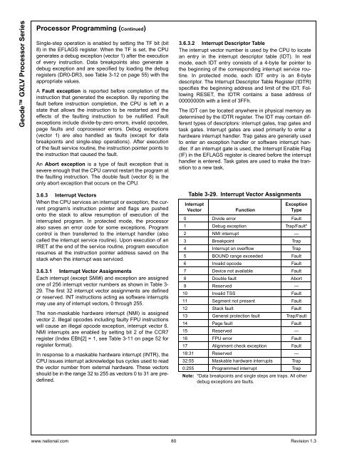
<strong>Geode</strong> <strong>GXLV</strong> <strong>Processor</strong> <strong>Series</strong><strong>Processor</strong> Programming (Continued)Single-step operation is enabled by setting the TF bit (bit8) in the EFLAGS register. When the TF is set, the CPUgenerates a debug exception (vector 1) after the executionof every instruction. Data breakpoints also generate adebug exception and are specified by loading the debugregisters (DR0-DR3, see Table 3-12 on page 55) with theappropriate values.A Fault exception is reported before completion of theinstruction that generated the exception. By reporting thefault before instruction completion, the CPU is left in astate that allows the instruction to be restarted and theeffects of the faulting instruction to be nullified. Faultexceptions include divide-by-zero errors, invalid opcodes,page faults and coprocessor errors. Debug exceptions(vector 1) are also handled as faults (except for databreakpoints and single-step operations). After executionof the fault service routine, the instruction pointer points tothe instruction that caused the fault.An Abort exception isatypeoffaultexceptionthatissevere enough that the CPU cannot restart the program atthe faulting instruction. The double fault (vector 8) is theonly abort exception that occurs on the CPU.3.6.3 Interrupt VectorsWhen the CPU services an interrupt or exception, the currentprogram’s instruction pointer and flags are pushedonto the stack to allow resumption of execution of theinterrupted program. In protected mode, the processoralso saves an error code for some exceptions. Programcontrol is then transferred to the interrupt handler (alsocalled the interrupt service routine). Upon execution of anIRET at the end of the service routine, program executionresumes at the instruction pointer address saved on thestack when the interrupt was serviced.3.6.3.1 Interrupt Vector AssignmentsEach interrupt (except SMI#) and exception are assignedone of 256 interrupt vector numbers as shown in Table 3-29. The first 32 interrupt vector assignments are definedor reserved. INT instructions acting as software interruptsmay use any of interrupt vectors, 0 through 255.The non-maskable hardware interrupt (NMI) is assignedvector 2. Illegal opcodes including faulty FPU instructionswill cause an illegal opcode exception, interrupt vector 6.NMI interrupts are enabled by setting bit 2 of the CCR7register(IndexEBh[2]=1,seeTable3-11onpage52forregister format).In response to a maskable hardware interrupt (INTR), theCPU issues interrupt acknowledge bus cycles used to readthe vector number from external hardware. These vectorsshould be in the range 32 to 255 as vectors 0 to 31 are predefined.3.6.3.2 Interrupt Descriptor TableThe interrupt vector number is used by the CPU to locatean entry in the interrupt descriptor table (IDT). In realmode, each IDT entry consists of a 4-byte far pointer tothe beginning of the corresponding interrupt service routine.In protected mode, each IDT entry is an 8-bytedescriptor. The Interrupt Descriptor Table Register (IDTR)specifies the beginning address and limit of the IDT. FollowingRESET, the IDTR contains a base address of00000000h with a limit of 3FFh.The IDT can be located anywhere in physical memory asdetermined by the IDTR register. The IDT may contain differenttypes of descriptors: interrupt gates, trap gates andtask gates. Interrupt gates are used primarily to enter ahardware interrupt handler. Trap gates are generally usedto enter an exception handler or software interrupt handler.If an interrupt gate is used, the Interrupt Enable Flag(IF) in the EFLAGS register is cleared before the interrupthandler is entered. Task gates are used to make the transitionto a new task.Table 3-29. Interrupt Vector AssignmentsInterruptVectorFunctionExceptionType0 Divide error Fault1 Debug exception Trap/Fault*2 NMI interrupt ---3 Breakpoint Trap4 Interrupt on overflow Trap5 BOUND range exceeded Fault6 Invalid opcode Fault7 Device not available Fault8 Double fault Abort9 Reserved ---10 Invalid TSS Fault11 Segment not present Fault12 Stack fault Fault13 General protection fault Trap/Fault14 Page fault Fault15 Reserved ---16 FPU error Fault17 Alignment check exception Fault18:31 Reserved ---32:55 Maskable hardware interrupts Trap0:255 Programmed interrupt TrapNote: *Data breakpoints and single steps are traps. All otherdebug exceptions are faults.www.national.com 80 Revision 1.3


